This thread has been locked.

If you have a related question, please click the "Ask a related question" button in the top right corner. The newly created question will be automatically linked to this question.

INA826: Current Measurement

Part Number: INA826
Other Parts Discussed in Thread: TINA-TI, INAEVM-ALT-SO8, INA821

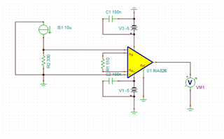
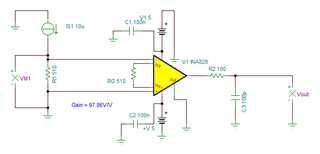
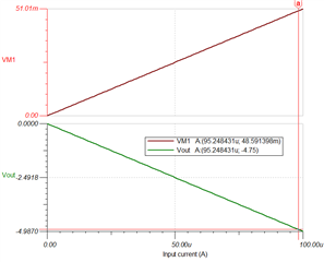
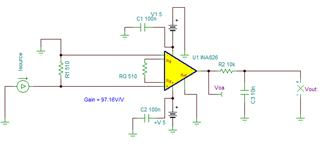
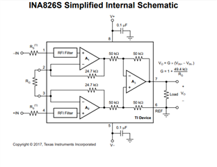
I am designing circuit to measure microamps of esp32 in sleep modes. I am beginner in this field. I am thinking of using INA826 amplifier. It will be used as low side sensing. Burden resistance is connected between ground of esp32 and negative terminal of supply voltage. Is my technique correct? And recommendation for some other amplifier. Thanks in advance.

  • HI Umar,

    The circuit as configured provides gain of ~97.86V/V.

    The output of the INA826 will be negative since the IN+ terminal is connected to GND and the IN- is connected to the positive side of the shunt resistor.

    The circuit works properly for an input current range of 0µA to ~98µA, producing a negative output voltage of 0V to -4.9V.

    If you require positive voltages, consider inverting the instrumentation amplifier input connections to the shunt resistor.

    Thank you and Regards,

    Luis

  • Thanks for the explanation. I am measuring output voltage with esp32 and it can measure maximum 3.3V.  Also i need to measure current in micro amps and milli amps range. I can change the burden resistor and also can set the gain accordingly. Value of C3 and R2 will staye same ?

  • Can i amplify few micro volts keeping in view noise?

  • Hi Umar,

    The RC low-pass filter at the output, reduces bandwidth and filters the broadband noise. There is a trade-off between noise and bandwidth; therefore, the RC output filter has to be set according to your application bandwidth and noise requirement.  You also have to consider the circuit stability when choosing the RC low-pass filter components.

    For example, on TINA-TI simulator, setting the low-pass filter with R=10kΩ, C= 10nF, limits the  AC circuit bandwidth to f(-3dB) = ~1.588kHz.

    When configuring the INA826 RG = 510Ω (Gain = 97.16 V/V) with this RC output filter, the TINA-TI simulated total output integrated noise is µVRMS is 83.28µVRMS. 

    This output noise corresponds to a very low-noise of 0.85 µVRMS referred to the inputs of the instrumentation amplifier:

     Input referred Noise: 83.28 µVRMS/ 97.16 V/V= 0.85 µVRMS 

    Applying a small-signal step signal (or square waveform) of 100nA produces a 10mVpp small-signal output transient response. The transient response is clean without excessive ringing and very low overshoot; showing the circuit is very stable.

    INA826_4-8-24_noise_bw.TSC

    Thank you and Kind Regards,

    Luis

  • Hi luis, 

    Thanks for the explanation. At low current (10uA) due to offset voltage, output voltage is higher than it should be. For 4uA inout it should be 4mA output but its around 9mA. How to solve this issue? And also how th the same circuit cab be used for high side current sensing ? I shall be gratfeul for the response. 

    Best Regards

    Umar Farooq

  • Hello Umar,

    Assuming you are using the INA826 with a 510Ω shunt resistor as shown on the original post, with a gain of 97.86V/V:

    The input stage offset is Vosi = 150µV (maximum) and the output stage offset voltage is Voso = 700µV (maximum) at 25ºC.  If we estimate the maximum total offset referred to the input of the device, the estimated total max offset referred to input is around  ~±150µV maximum.  Keep in mind, typically, the INA826 input referred offset will be closer to ~40µV as specified on the data sheet. See input referred offset calculation below from maximum offset specifications.

    Since the max worst case input referred offset around ~150µV across the 510Ω shunt resistor, this accounts for a current measurement error of ~0.294µA.  I don't follow the explanation about the 4mA and 9mA output since the INA826 provides a voltage output.  What is the accuracy/tolerance of the RG resistor? Are you using your own PCB layout or the INAEVM-ALT-SO8 PCB board to perform the measurements?  If using your Custom PCB board, can you please post your schematic and PCB layout? What precision meter or ADC device are you using to measure the INA821 output?

    A common technique to correct for the offset error is to perform an offset null measurement.  In other words, measure the output of the INA826 while ~0µA current is flowing through the shunt resistor. This offset null measurement is stored and can be subtracted while performing subsequent measurements to cancel the offset error.

    Regarding the high-side current sensing question:

    What is the high-side maximum common-mode voltage and max differential voltage? Keep in mind the INA826 will have a limited range while being powered with the ±5V supplies. The Analog Engineers Calculator can be helpful to determine the INA826 linear input common-mode range, the tool is available for download on the link below:

    https://www.ti.com/tool/ANALOG-ENGINEER-CALC

    Due to the complexities of the 3 amp instrumentation amplifier it can be difficult to understand the min and max operating ranges of the input and output with various gains, reference voltages, supply voltages and input common-mode conditions. For this reason we often use  the engineering calculator tool in order to determine the INA826 linear operating range for the circuit conditions. Below you can see the simplified schematic. 

    Using the "Vcm vs. Vout for Instrumentation Amp" calculator, the user can enter the INA826 conditions for power supplies, gain, Vref voltage and input common-mode voltage (Vcm) and determine the valid input range. The calculator provides the max and min input differential signal range that can be applied to the INA826 in the particular circuit configuration.

    For example, powering the INA826 with VS+ = +15V and VS- = -5V, VREF=0V, Gain = 97.86V/V, can allow the high-side shunt resistor an input common mode of ~+11.5V while allowing a maximum differential voltage of +50mV:

     Please find below the TI Precision lab series on Instrumentation amplifiers. The three amp theory covers the topology of the INA826, but the video series provides a summary other instrumentation amplifiers topologies and a explanation of the linear range and trade offs that may be useful.

    Precision labs series: Instrumentation amplifiers

    Thank you and Regards, 

     Luis

  • Hi

    Thanks for your valuable time and explanation. It helped alot.

    Best Regards