This thread has been locked.

If you have a related question, please click the "Ask a related question" button in the top right corner. The newly created question will be automatically linked to this question.

OPA355: Amplifiers forum

Part Number: OPA355

HI team,

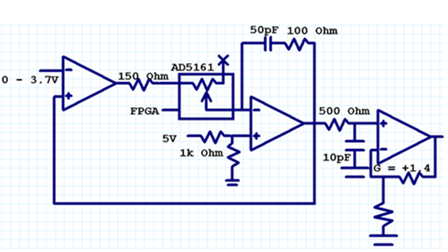
My customer use OPA355 to design as below circuit.

But due to AD5161 is a adjust resitance. might be parasitic capacitance of AD5161 to cause some delay here. 

so do you have suggestion here?  change OP solution or add  Compensation circuit? 

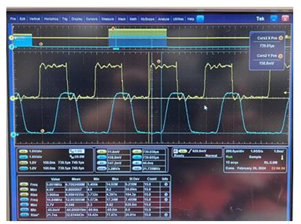
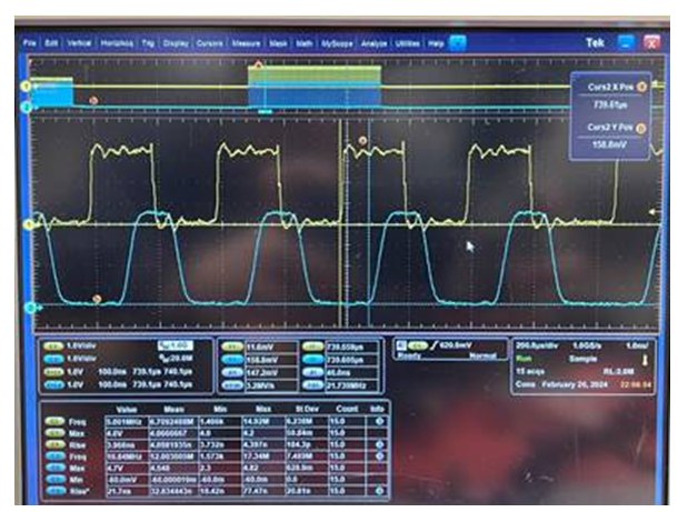
yellow is a input signal

blue is a output signal
add simulation waveform here. they wants to control dv/dt. right side pic is okay for them.

  • Hi Jimmy,

    Are all the amplifiers in the design OPA355? Also, it is hard to read any numbers in the oscilloscope screenshot you sent so it is hard to tell how much delay there is between input and output. Can you share what this measurement is?

    Thanks,

    Nick

  • Hi team,

    All OP are OPA355. the delay is 79ns. 

  • Hi Jimmy,

    Thank you for providing these details. Have you tried testing the delay between the input and output signals by removing the AD5161 and dropping in just a standard, fixed resistor value? The delay could be a result of the I2C interface of the AD5161.

    Thanks,

    Nick

  • Hi team,

    If cusotmer uses fix resistor is oaky. when AD5161 control resistor stable. the delay still happen.

    Customer use other OP like ADA4855 will improve to 40ns of delay. 

  • Hello Jimmy,

    What is the performance difference (in terms of delay) between using the fixed resistor and the AD5161?  I understand the OPA355 has a 79ns delay with the AD5161.  What is the delay with the fixed resistor?

    For the ADA4855, is the 40ns delay with the fixed resistor or the AD5161 digital pot?

    Could you also explain your circuit gain for each amplifier stage?  

    Is your input signal 2MHz?

    What is the highest resistor selection you will use for feedback resistor and gain resistor?

    Best,

    Alec

  • Hi team,

    1. The biggest difference between a general resistor and AD5161 (variable resistor) is that there will be a pF-level parasitic capacitance to ground on both sides of the AD5161 resistor Pin, because the parasitic capacitance on both sides will cause circuit oscillation and affect the output delay, so when using Generally, the resistor will only have the Propagation Delay of the OPA itself affecting the output.
    2. Gain is not specially considered during the design. According to the circuit configuration, the OP Gain of the second stage should be about 3v/v, and the Gain of the last stage = 1.4v/v.
    3. The input frequency is 2MHz
    4. The only thing that will change in the circuit is the resistance value of AD5161, which can reach a maximum of 9 kΩ.

  • Hi Jimmy,

    The input capacitance of the ADA4855 is lower than that of the OPA355 which likely contributes to a lower propagation delay as there is less capacitance to drive. To decrease the propagation delay, reducing capacitance by optimizing layout could help make a difference.

    Thanks,

    Nick

  • Hi team,

    Does TI have a better solution than ADA4855? Thanks 

  • Hi Jimmy,

    What are the requirements of the op amp you are looking for? We do have some op amp solutions with lower input capacitance and I can point to op amps based on other application requirements.

    Thanks,

    Nick

  • Hi Nick,

    Base on ADA4855 spec. like slew rate, BW, rail to rail. output current. Thanks