This thread has been locked.

If you have a related question, please click the "Ask a related question" button in the top right corner. The newly created question will be automatically linked to this question.

INA851: Gain error

Part Number: INA851

Hello, I am using the INA851 in a 0.4 overall gain, that is Gout = 0.2 and Gin = 2. I am looking for the gain error of this configuration.

The datasheet states:

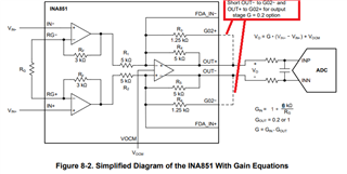
- gain error is +/- 0.1% with G = 0.2. I am assuming that this is mainly the accuracy of the second stage when set in a G = 0.2 (that is G02+ and G02- connected to their respective OUT).

- gain error is +/-0.02% with G = 1. That looks like the combined accuracy of the two stages in their ideal (best accuracy) configuration

First, I was expecting the 1.25K embedded resistors to precisely match the 5K ones, and when configured in G=0.2 the accuracy would not degrade that much, that is from +/-0.02% to +/-0.2% (one magnitude). Is there something I am missing here ?

Then finally

- gain error is +/-0.2% with G > 10. That would be mainly the accuracy of the first stage with a perfect RG connected and Gout = 1.

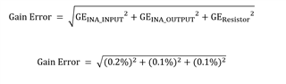
For the sake of this discussion, let's assume I have Gout = 0.2 and Gin = 10 (yes I know, there is a better combination), then is the overall accuracy computed by adding 0.1% for Gout and 0.2% for GIn, that is 0.3% total ? (not e that knowing that the overall part performance is 0.02%, I neglect combined effects between Gin and Gout).

If this is not correct, then how should I compute the gain error ?

Best regards

Pascal

  • HI Pascal,

    Yes, the INA851 offers the lowest gain error at G=1 since there are no external resistors involved, no external connections involved, and the internal resistors of the INA851 are ratiometrically matched. Therefore, at G=1 the error is ±0.02% maximum with ±5ppm/°C drift.

    - On the G=0.2V/V configuration, the internal 1.25kΩ is connected in parallel with the internal 5kΩ resistor via an external connection, by connecting the G02+ to OUT+, and  G02- to OUT- as shown below. 

    As you have mentioned, the specified gain error in this configuration is ±0.1%.  Although the 1.25kΩ and 5kΩ internal resistors are carefully and ratiometrically matched in the IC internal layout to provide the lower gain error, since this configuration involves an external connection routed through the package wire bond connections, the package pins, and the external PCB connections, these additional connections add some variation on the series resistance producing a small error. Therefore, the gain error at G=0.2 configuration is a conservative ±0.1% max specified on the datasheet.

     - Adding the Gain errors directly tends to provide a very conservative estimate of gain error. The compounded probability of the input stage, output stage and resistor tolerance all being near their worst tolerance at the same time is very small.  Keep in mind, the compounded probability that all three sources of error are near the max tolerance, is the product of the three small probabilities, resulting in a very small compounded probability.    

    The root-sum-of-squares is an operation commonly used in industry when combining errors from uncorrelated sources to obtain an estimate of error. When estimating the gain error accounting for the external resistor tolerance, the input stage gain error, and the output stage gain error, you may consider using the root-sum-of-squares. The root-sum-of-squares tends to provide a more realistic estimate of error. Rather than adding the maximum values, the standard deviation of uncorrelated Gaussian distributions can are combined as the square root sum of the squares. 

    On your example, you could use the below to estimate Gain error, when the input stage is set on GIN=10, GOUT=0.2, and accounting for the resistor tolerance. Assuming the RG resistor has a  ±0.1% tolerance, the estimated gain error calculated from the maximum specs using the RSS is ~0.224%.  See calculation below.  


    Edit 4/9/2024: Corrected calculation, input stage gain error is ±0.2% at G=10 per INA851 data sheet

    Also, on the estimate above, we used the maximum data sheet specifications to estimate the maximum overall gain error.  The INA851 typical performance gain error is much smaller.

    Thank you and Regards,

    Luis   

  • Thanks Luis for the extensive answer.  

    I missed the uncertainty in the 1.25k external connection. I will then also compute an uncertainty estimate for the input gain when G is between 1 and 10 to not overestimate the error.

    Pascal

  • Thank you Pascal,

    Attached is a short presentation regarding error analysis statistics/estimates. Although this presentation is not related to the INA851, you may find it useful, as it discusses the statistics behind the specifications and error estimates.

    Error_Analysis_statistics_4-9-24.pdf

    Also, below is a link to an Application Brief that showcases an INA851 circuit example, and provides the estimated DC accuracy calculations from max data sheet specs, and also an estimate based on typical specs.  The calculations are shown on Table 3, page 5.

     Optimizing Strain Gauge Accuracy With INA851 vs. Discrete Design

    Thank you and Kind Regards,

    Luis,