This thread has been locked.

If you have a related question, please click the "Ask a related question" button in the top right corner. The newly created question will be automatically linked to this question.

AMC1301: AMC1301 for AC sensing

Part Number: AMC1301

Hi Team

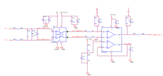
I am using the AMC1301DWVR to sense AC voltage. We are designing an inverter whose output AC voltage is 240 volts. This voltage, we are trying to sense by using AMC1301. A circuit diagram is given below. 

Can someone check this circuit and let me know if I am good to use this circuit for AC sensing?

  • Hi Hariom,

    A few things:

    1. You might want to add an input filter to remove potential noise.  See image below and section 8.2.2.2 of the datasheet.
    2. Adding an additional 1uF cap on the input would also be helpful for keeping the supply stable.
    3. You might want to increase your resistor divider values to reduce power losses.
    4. Based on your resistor value choices, you seem to be going past the full-scale range of the device.
    5. Since you are planning to measure voltage it may be better to use a higher input impedance device like the AMC1331. Otherwise you would have to account for the lower input impedance gain and offset errors.

    Thanks.

  • Hi Saleh

    As per your suggestion, i made bit modification to circuit. I have done simulation and proof of concept for the following circuit, and I am getting the expected results. But I want to understand how the AC signal is amplifying in this circuit since we are  not giving any negative supply to the iso-amp. 

  • Hi Hariom,

    You'll probably want the below resistors to make the filter effective.

    Is the 240V that you mention rms or peak.  Assuming 240Vrms, the peak voltage across the device inputs right now is: 240V*1.41*(1k /1241k) = 273mV.  The linear range of the inputs of the device is +-250mV.

    I can't give details on the inner-workings of the device, other than what's shown in the datasheet, without some NDA's.  

    Thanks.