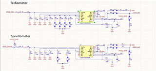
This thread has been locked.

If you have a related question, please click the "Ask a related question" button in the top right corner. The newly created question will be automatically linked to this question.

LM2917-N: Review the circuit for Tachometer and Hall effect Speed sensor

Part Number: LM2917-N

Hi,

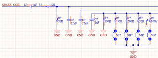
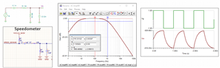
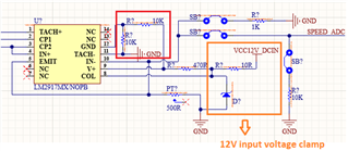
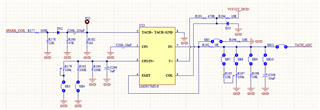
Just to be double sure some guidance is needed to validate the circuit as much help is not available. This tachometer and speedometer would be for motorbikes only. For speedometer hall effect sensor is used and for tachometer wire on the spark coil will be wound of around 18SWG 50 turns. Solder bridges are just for options during debug.

  • Hi Basit,

    Please provide me the design requirements --> I assume that this is frequency to voltage conversion application. What are the input frequency and output voltage ranges for the application.  

    For speedometer hall effect sensor is used and for tachometer wire on the spark coil will be wound of around 18SWG 50 turns.

    You have speedometer and tachometer that are listed at the input. In the English language, both words mean the same things. Tachometer displays the engine speed, whereas the speedometer displays the speed of the vehicle. 

    You mentioned that tachometer wire on the spark coil will be wound of around 18SWG 50 turns. The spark coil will generate high voltage arc whenever the coil is deenergized from Ldi/dt change, even when the spark coil is energized. That volage arc may be 1000s V to kV that will ionize the air. I hope that this is not the input that you are going to send to the LM2917-N's input terminal. There is no volage spike protection at the input and it will damage the LM2917-N

    Anyway, I may be provide a simplified simulation if you are able to provide me with input and output design requirements. If you have other questions, please let me know. 

    Best,

    Raymond

  • Hi Raymond,

    From tachometer, I meant to say the engine rev RPM. I plan to wrap the wire around the LT side of the ignition coil of motorcycle. Maybe I may have to add a diode at the input. I am not exactly sure about the frequency range but probably it will lie in the 0-10KHz range. The output voltage range I need is between 0V-3.3V.

    From the speedometer prespective I will be using an after market hall effect sensor and attach to the bike wheel. The frequency would be probably in 0-1000Hz range. The output voltage range needed here is also 0V-3.3V.

    For engine rev RPM meter I am referencing this circuit:

  • Hi Basit, 

    Enclosed is the LM2917's application note and it may help you. 

    https://www.ti.com/lit/an/snaa088/snaa088.pdf?ts=1713540639443&ref_url=https%253A%252F%252Fwww.google.com%252F

    From the speedometer prespective I will be using an after market hall effect sensor and attach to the bike wheel. The frequency would be probably in 0-1000Hz range. The output voltage range needed here is also 0V-3.3V.

    Please take a look at the input. It needs to be close to squarewave. You have HPF and LPF at the input, both poles need to be widen a bit for the application. The HPF will affect the low speed and LPF will attenuate the high speed. 

    The same input filter will not work for 0-10kHz input from tachometer. 

    Motorcycle Vin 04192024.TSC

    Please take a look at the following section. 

    The output ripple voltage is determined by the transfer function. Also see the application note. 

    Here is the simulation. The model is very simplified and you will need to check it out on a test bench. Since I do not know what your input looks like, the input signal is configured arbitrarily. 

    LM2917-14 1kz to 3.3V 04192024.TSC

    If you have additional questions, please let me know. 

    Best,

    Raymond

  • It will be a test case then. I was looking for different references and found one option below. Any calculation that you can provide?

  • Hi Basit, 

    The 8 pin LM2907 has the following options. Please select one that is best suited for your application. 

    Here is a simulation example that may be used for your application. The calculation R1, C1 values are similar to the previous reply. 

    LM2907_F2V 04252024.TSC

    If you have other questions, please let me know. 

    Best,

    Raymond