This thread has been locked.

If you have a related question, please click the "Ask a related question" button in the top right corner. The newly created question will be automatically linked to this question.

OPA2171: Output doesn't match the input in certain working condition

Part Number: OPA2171
Other Parts Discussed in Thread: OPA2607, OPA2991, OPA2992, OPA2990

Hi team,

Customer use OPA2171 to sample the primary current in LLC topology.

They use to parallel LLC to extend the power, and OPA2171 is used to sample two primary current in the resonant tank.

When the output voltage is 650V and add full load at the output, OPA2171 have a certain possibility that output voltage can't match the input.  Frequency is 122K.

But if they change to OPA2607, everything will be good. OPA2607 have less Offset.
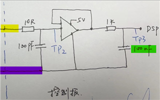
Schematic:

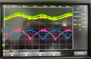
Yellow: primary current 1  Green: Primary current 2  Blue and Purple: Output of OPA2171

OPA2607: Blue primary current, purple: OPA2607 output

OPA2607.jfif

  • Hello Yishan, 

    This is unexpected behavior, the OPA2607 is decompensated op amp therefore it requires at least a gain of 6.

    The configuration you have drawn is a gain of 1. Please confirm the circuit is as drawn. 

    Also, please specify the voltage at the yellow point (the frequency is 122kHz) and the is the purple ground (relative to the 5V)? 

    All the best,
    Carolina 

  • Hi Carolina,

    I have checked with customer. The input of amplifier is 0-2V and all the secondary side is the same ground.

    I am not very sure what is the expected results about the output of amplifier. I will check with customer about that.

    So far do you find anything wrong in their schematic? (OPA2171 is the same schematic)

    Thank you

    Yishan Chen

  • Hello Yishan, 

    Thank you for the additional information.

    I ran a couple sims and it looks like I am running into stability issues even with the RISO present.
    Have the customer remove this capacitor and let me know if this delivers their desired behavior: 

    All the best,
    Carolina 

  • Hi Carolina,

    Me and customer have do some test to find the issue.

    Nothing change if we remove 100nF capacitor. But I think maybe the reason is because of the slew rate.

    When we lower the signal amplitude and keep the same frequency, the output can follow the input very well.

    But if we raise the signal amplitude, the output will be like a triangle wave and input is the sine wave at the same time.

    So we do a few test to check if it is really a slew rate problem. When the input sine wave changed more softly, I think the output can follow the input better.

    Please check the image.

    Blue is the original signal, Yellow is the input of OP AMP and Green is the output.

    Therefore, could you please provide another device which is P2P with OPA2171 and familiar parameter only with higher slew rate? (This is urgency)

    Thank you

    Yishan Chen

  • Hey Yishan, 

    Thank you for the additional information. Looking specifically at the last image, the needed slew rate is 1.19V/us. 

    The customer may also reference the full power bandwidth of the part located on Figure 35 of the datasheet. At the given Vpp (2.5V), the max frequency the OPA2171 can support is a little less than 100kHz (which is less than the desired 122kHz):

    I recommend the customer try the OPA2991: 

    All the best,
    Carolina

  • Hi Carolina,

    We have switched to OPA2991, but it seems it still have some mismatch issue.

    Do you have any idea here?

    Green and yellow is the input signal, Blue and pink is the output signal.

    We keep the 1K resistor and remove the capacitor and send to MCU directly.

    We have removed all the load to do the test.

    but it still have some delay here.

    Thank you 

    Yishan Chen

  • Hello Yishan, 

    Has this also been removed? 

    It will introduce delay also. 

    All the best,
    Caro

  • Hi Carolina,

    We have removed the resistor and capacitor to do the same test .

    The results is the same.

    Because customer need to do the product final test and It has not been resolved for so long.

    Maybe we will lose this socket at last.

    Do you have any advise here?

    Yishan Chen

  • Hey Yishan, 

    I recommend the customer change from the OPA2991 to the OPA2992. Here are test results: 

    2.21V, 900kHz (blue is input, yellow is output): 

    OPA2990

    OPA2991

    OPA2992

    The slight mismatch at the bottom of the signal (0 Vand V-) is where the output tries to go to V- and cannot due to headroom, there is some overload recovery time associated and then the output recovers back onto the signal. 

    Hopefully this helps us keep the socket. Please let me know if there is additional testing required. 

    All the best,
    Carolina

  • Hi Carolina,

    Thank you very much for your support. The issues is solved properly. But here is one phenomenon we want to discover.

    The two channel input signal is around 110K and the phase different is about 180degree, but the output signals are in the same phase.

    What is the reason?

    Blue and purple are the input signal, Green and yellow are the output signals.

    Thank you 

    Yishan Chen

  • Hello Yishan, 

    Happy to hear the customer is evaluating with the OPA2992, could you please confirm that the setup is like this? 

    All the best,
    Carolina 

  • Hi Carolina,

    Yes, they connected 100nf capacitor and 1K resistor at the output.

    Thank you

    Yishan Chen

  • Hey Yishan, 

    That's interesting, I will try to recreate it in lab. 

    All the best,
    Carolina

  • Hey Yishan, 

    My equipment has been under calibration in the lab. I expect them to become available tomorrow or the next day. 
    Please expect a response by 06/20 EOD. 

    All the best,
    Carolina

  • Hello Yishan, 

    We have some preliminary results but require additional testing. What I read from the oscope is that the input is 2Vpp at 285kHz, could you please confirm? 

    All the best,
    Carolina 

  • Hi Carolina,

    The input signal is from 0.1V-1.8V and the switching frequency is about 260Khz.

    Thank you

    Yishan Chen

  • Hello Yishan, 

    I confirmed the distortion the customer is seeing in lab. 

    This is due to the RC filter formed by the output, R=1k and C=100nF, has a low pass filter of -3dB of 1591Hz. 
    Is the customer open to changing this value? I can help calculate the minimum Riso needed to stabilize the circuit without filtering out the entire signal. 

    All the best,
    Carolina

  • Hi Carolina,

    Thank you very much.

    Could you explain why the RC frequency response causing this results?

    I found the output signal frequency is similar to the input signal frequency, if the -3db frequency is in 1591Hz, I think when the input signal frequency is higher enough, all the output signal will have 90 degree phase shift, but they will still keep the phase difference.

    Could you please help me with this concern?

    For the RC value, I think we can keep this right now since no system failure from customer side.

    Thank you again.

    Best Regards,

    Yishan Chen

  • Hey Yishan, 

    The RC low pass filters are not the same: 

    The following use this online calculator: RC and RL Passive Filter Calculator | DigiKey Electronics

    For the input: 

    For the output:

    Although the first filter allows most frequencies through, and the OPA2992 supports "2.21Vpp, 900kHz" as proven earlier in the post, the output filter significantly dampens anything past 1.5kHz. 

    I think the difference in communication and what the customer is seeing may be due to the hand-drawn circuit. Could the customer please share the actual schematic? We can move this thread internally if that makes the customer more comfortable. 

    All the best,
    Carolina

  • Hello Yishan,

    This circuit seem to be very unusual to me. Input signal is 122kHz and gets doubled by full wave rectification. 2nd step is low pass filter at 160MHz, in other words do almost nothing. 3rd step is to buffer 244kHz (with harmonics) with a risk of overdrive recovery delay (if op amp output voltage reaches VOL or VOH). 4th step is a low pass filter set to 1.6kHz which will give the average voltage of a 244kHz signal.

    This makes the op amp work work quite hard (at high speed) when the goal was just to average to input voltage to a DC value, something a slow op amp could do easily.

    Replace the 10 ohms and 100pF with a much lower LPF, for example 1k and  100nF