This thread has been locked.

If you have a related question, please click the "Ask a related question" button in the top right corner. The newly created question will be automatically linked to this question.

LMV321: LMV321

Part Number: LMV321

Hi ,

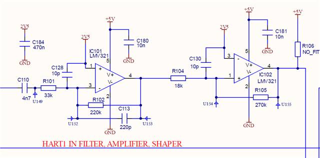
We are using the part LMV321 for one of our development project. We are using LMV321 to filter the HART signals (4 to 20mA analog) with the frequency range of 1200Hz to 2200Hz.Currently we are using 5V supply to power the op-amp. Now we are migrating from 5V to 3.3V logic compatible microcontroller. Need support for redesigning the filter with 3.3V supply and design calculations. Attached schematic snapshot for reference.If the part LMV321 is not compatible to operate with 3.3V supply, please suggest an alternate part with 3.3V supply compatible.

Kindly respond as early as possible.

Thanks & Regards

Mahalakshmi S

  • Hi Mahalakshmi, 

    Could you help to confirm a few things to clarify: 

    • Can the reference voltage 2.5V be modified to change to mid-supply? 
    • Is R106 populated or not? 
    • What is the desired output voltage (voltage and frequency)? 
    • Is the second op amp stage intended to be a comparator circuit? I see that there is a positive feedback loop. 

    Please let me know if you have any questions.
    Thank you!

    Best Regards,
    Ashley

  • Hi Ashley,


    Thanks for your quick response. Please find the below clarifications and attached schematic reference FYI.


    • Can the reference voltage 2.5V be modified to change to mid-supply? 

    We are using 2.5V midpoint reference voltage which needs to be compatible for other two slave devices also. So we cannot change the reference supply.

    • Is R106 populated or not?

    R106 is not populated 

    • What is the desired output voltage (voltage and frequency)?

    We are interfacing 4-20mA (0 to 5V logic) analogue measured variables (HART signals) with the range of 1200hz to 2200hz frequency. During Signal transmission the input voltage of the op amp will be around 2.5V

    • Is the second op amp stage intended to be a comparator circuit? I see that there is a positive feedback loop. 

    The output of LMV321 is connected to two different circuits

    1.HART IN Filter – Used as Schmitt trigger, to digitalize the output of LMV321(IC101) to be fetched into microcontroller

    2.HART OUT Generator – To extract the digitalized signals from the microcontroller to HART Compatible for signal transmission

  • Hi Mahalakshmi, 

    Thank you for the additional information. Could you re-attach the schematic reference? I do not see it linked in your post. 

    • Is the second op amp stage intended to be a comparator circuit? I see that there is a positive feedback loop. 

    The output of LMV321 is connected to two different circuits

    1.HART IN Filter – Used as Schmitt trigger, to digitalize the output of LMV321(IC101) to be fetched into microcontroller

    2.HART OUT Generator – To extract the digitalized signals from the microcontroller to HART Compatible for signal transmission

    To clarify my question, I am trying to understand why you have connected the second op amp with positive feedback. What is the intended output for this circuit? 

    Regards,
    Ashley