This thread has been locked.

If you have a related question, please click the "Ask a related question" button in the top right corner. The newly created question will be automatically linked to this question.

OPA637: the function of the feedback loop in parallel capacitor

Part Number: OPA637

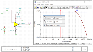
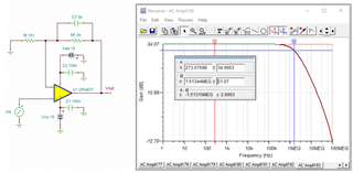
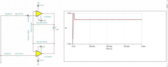
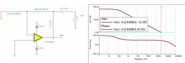
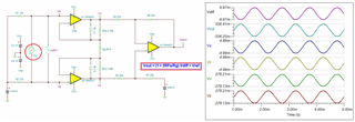
Hi, the OPA637 gives the following application circuit, I don't quite understand what is the role of the 3pF capacitor, is it to play the role of phase compensation, how is its value calculated, and how to consider the stability of the first stage circuit here? thanks.
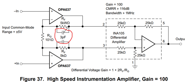
  • Hi Zac, 

    how is its value calculated, and how to consider the stability of the first stage circuit here?

    OPA637's datasheet is specified GBP at 80MHz. Based on the simulation below, Gains = 49.505V/V and the pole at -3dB = 1.78MHz. The simulated GBP should be approx. 49.505*1.78MHz = 88 MHz as typical. 

    When 3pF is placed across the 5kΩ feedback resistor, it limits the bandwidth of the op amp, where the OPA637's dominated pole is limited to, fp = 1/(2*pi*5kΩ*3pF) = 10.6 MHz, where is the GBP product is limited to approx. 1.5MHz * 49.505 = 74 MHz. The simulation is shown the following behavior. 

    OPA637 IA 04252024.TSC

    If the application does not require to have the wide BW, then an op amp circuit may limit the BW for an application. The benefit of such practice is to attenuate unwanted noises after the pole at -20dB/decade for single op amp. For 3X IA op amps, the high frequency noises are attenuated at least -40dB/decade, perhaps at -60dB/decade or steeper depend on a design.  

    Regarding to the stability, you have to perform AC stability analysis. Based on the AC response, the single OPA637 above should be stable. 

    The Figure 37 demonstrates how OPA637 may be used to construct an instrumentation amplifier in discrete configuration. In practice, it does not pay for build a discrete IA. The feedback resistor values in the first stage have to be absolutely matched, and the feedback resistor values on the 2nd stage have to be ratiometrically matched. This means that you have to implement ultra precision discrete resistors up to 0.01% to enhance CMRR performance. These are difficult to accomplish in a discrete PCB board. It is a easier to be designed and implemented on a Si die, where these critical components are well matched, trimmed over wide temperature range. 

    If you need high BW IA, please consider INA849, INA848, INA821 products. 

    Enclosed is the TI op amp related training videos, which it includes 9 op amp stability video clips on the topic. 

    https://www.ti.com/video/series/precision-labs/ti-precision-labs-op-amps.html

    https://www.youtube.com/watch?v=ulm_FPK0jiE

    If you have additional questions, please let me know. 

    Best,

    Raymond

  • Hi Raymond

    Thanks for your reply.

    As you said, the GBP has decreased from 88MHz to 74MHz, but I am still confused about my application.

    I am using opa637x2 to build an instrument amplifier with an amplification factor of G=1+2.49K/90.9=28.39. When I simulated it, it performed well with a grounded input and an output of 1.42mV. The calculated input is 1.42mV/28.39=50uV, which is the Vos I set.

    I simulated its stability, with a phase margin of 81.83, and I believe it meets stability requirements

    I built it on the circuit board, with the input grounded and the output having a large value. I measured the displayed value with a multimeter to be 0.23V (that is, Vd in figure1), and it will continue to decrease, I observed it decreasing from 0.23V to -0.12V, which should be incorrect, but I am not sure where the problem lies because the stability simulation is good.


    I tried to add a 3pFx2 capacitor to the feedback loop and found that it returned to normal, which confused me. It seems that it has changed from an unstable state to a stable state. However, as I just mentioned, the stability of this circuit is good.


    It is possible that my stability analysis is incorrect because I am not sure if the stability of the first stage of the instrument amplifier is the same as the stability of a single amplifier connection. Therefore, my question is how to simulate the stability of the instrument amplifier and can you provide some analysis of the problems that have occurred in my actual circuit. Thanks.

  • Hi Zac,

    The IA is very sensitive circuit and please pay attention of balance of the input impedance, which is the CMRR that I mentioned in the previous reply. 

    When you calculate the combined Gains, the G=1+2*2.49K/(2*90.9)=28.39 V/V, where Rg = 2*90.9Ω per your simulation. Or you need to place GND node in the middle of 2X Rg in series. 

    OPA637 Zac IA 04282024.TSC

    In addition, the common mode voltage, Vcm needs to be established correctly for the linear operation. Since you are using ±15Vdc, Vcm = 0 is ok and valid. If you use asymmetrical supply or single supply rails, the Vcm will change and you need to pay attention to it. 

    Here are our additional IA videos.

    https://www.youtube.com/watch?v=ulm_FPK0jiE&t=373s

    https://www.youtube.com/watch?v=fZmPV4Oh7lg

    https://www.youtube.com/watch?v=ktKTxEsQzlg

    https://www.youtube.com/watch?v=NvyDw8ZpLd0&t=338s

    If you have other questions, please let me know. 

    Best,

    Raymond