Part Number: INA260
Hi expert.
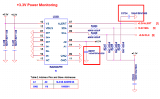
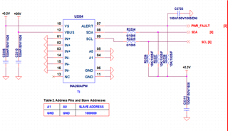
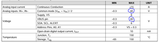
My customer would like to use INA260A to detect voltage(36V).
the schematic configuration is as below. please review it
please let me know what needs to be revised.
thanks
Part Number: INA260
Hi expert.
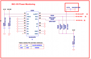
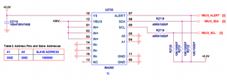
My customer would like to use INA260A to detect voltage(36V).
the schematic configuration is as below. please review it
please let me know what needs to be revised.
thanks