Other Parts Discussed in Thread: THS4541, TINA-TI
Hello,
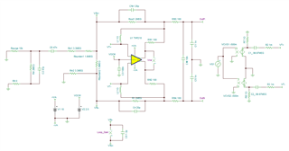
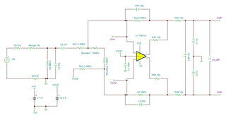
I plan to use THP210 for a energy power metering application. Sensor connected to THP210 present a very high output impedance (sensor are capacitors divider for kV voltage application).
Then I should use very large value resistor for input and feedback. In the range of mega ohm.
The THP210 will be used to made a single ended to differential conversion with a negative gain of approx -4.4dB.
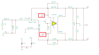
Rin resistors about 3.3mega ohm, Rfb about 2 mega ohm and a small capacitor of 20pF in // with Rfb.
I will use a specific layout to avoid parasitic stray capacitance, especially in the area of inputs of THP210, I don't know if I should take another consideration to achieve a such design, but when I read following statement on datasheet I try to get the TI training but can't find it:
High feedback resistor values (RF > 100 kΩ) interact with the amplifier input capacitance to create a zero in
the feedback network. Compensation must be added to account for potential source of instability; see the TI
Precision Labs FDA Stability Training for guidance on designing an appropriate compensation network.
I can't find FDA stability training on TI website, the only video I found is relative to gain and phase margin, no mention of large value feedback resistor and stability.
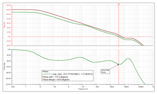
How we can define criterion for stability in terms of phase margin/gain margin in a attenuator configuration ?
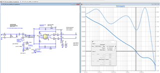
Example (I use LTSpice simulator) Bode diagram of my circuit:


