Gentlemen:
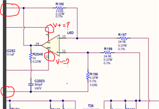
I recently had to add an RC snubber to the output of a differential amplifier (LM124) which is used as a feedback sense of the output voltage of a high frequency (900Khz) switching Buck regulator. The value of the snubber is 560pf and 10 ohms. I did this (and I don't like adding it!) to alleviate the switching noise that seems to get coupled into the output of the diff-amp. I would like to know what the maximum capacitance is that I can safely use that would not risk instability of the diff-amp (LM124).
BTW, this switching noise, which is directly dependent on the dv/dt of the switching transistor seems to be coupling in via the bias supplies (+12V, -0.7V), and not the inputs. Beefing up the bypass caps on the supplies helped but did not eliminate the noise coupling.
Any insight into this phenomenon would be greatly appreciated.
Thank you,
Richard Cummaro
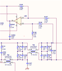
Schematic:
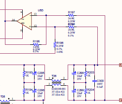
LM124 for output voltage sense