This thread has been locked.

If you have a related question, please click the "Ask a related question" button in the top right corner. The newly created question will be automatically linked to this question.

PGA855: CMRR at 100kHz

Part Number: PGA855

Hi TI,

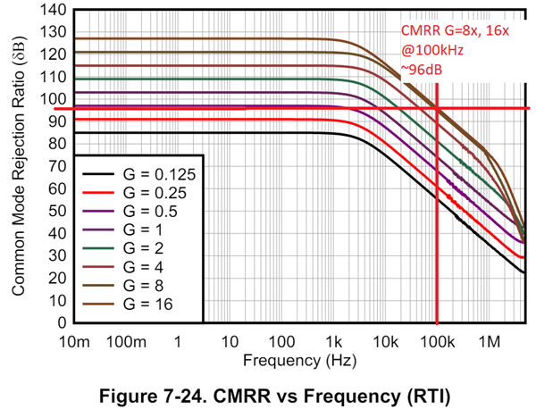
Referring to this plot, I am expecting the CMRR at 100kHz to be similar for gain of 16 and gain of 8, about 96dB ish
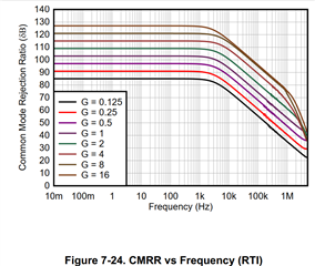
I am characterizing the device on its EVM, powered from ±15V, what I find is that, at a gain of 8, the CMRR is significantly better at 100kHz:
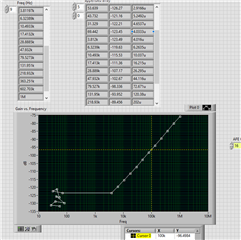
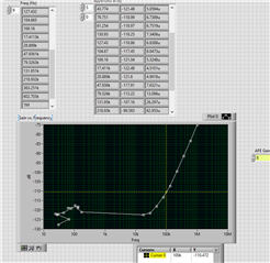
-96dB vs -110dB. 

Am I making the correct measurement? 

  • Hi Hao,

    The PGA855 CMRR performance in figure 7-24 is typical, and some device variation is expected. Nevertheless, I expect the CMRR to be closer to 96-dB result, CMRR at -110dB at 100kHz seems optimistic.

    What is the amplitude of the signal applied at the input of the PGA855?  Is this ±10Vp? Is this using the standard ±15V supply condition listed on the data sheet?

    I have used  the Keysight 33500B function generator to generate a ±10Vp input signal to measure CMRR at G=16x up to 10khz, for another Customer request; and obtained results around ±4dB from typical spec. The output result was measured using an oscilloscope substracting CH1 (OUTP) and CH2 (OUTN). Keep in mind, on the PGA855EVM bench set up in that example have some noise measurement limitations since I was not using a specialized differential probe; nevertheless, the measurements result were reasonably close to the typical datasheet expectation. I will see if I can provide a CMRR measurement at G=8x F=100kHz mid next week. 

    Thank you and Regards,

    Luis 

  • Hi Hao,

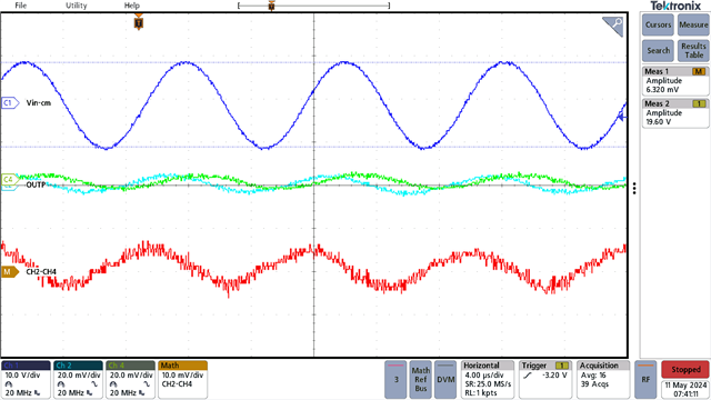
    On the PGA855 bench setup, the input and output filters of the PGA855EVM were removed, and the inputs of the PGA855EVM were shorted by replacing the differential input capacitor with a 0Ω resistor; in other words, placing a short right at the PGA855 inputs. Applied a 100kHz, ±10Vp common-mode signal, with the PGA Gain=16x. The output is measured using an oscilloscope substracting CH2 and CH4.  The output is around 6.32mV peak to peak.  This corresponds to a CMRR (RTI) of ~94.09dB. See oscilloscope plot at G=16x:

    G=16x, VIN_CM = ±10Vp (20Vpp), Vout= ±3.16mV (6.320mVpp)

    CMRR = ~94.09dB @ G=16x

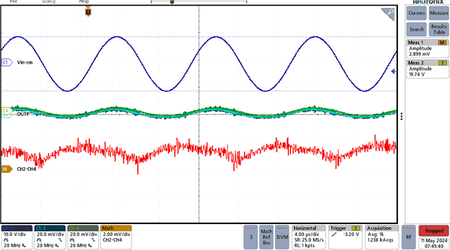
    On the second oscilloscope plot below, PGA G=8x. The output is around 2.899mV peak to peak. This corresponds to a CMRR (RTI) around ~94.84dB.  

    G=8x, VIN_CM = ±10Vp (20Vpp), Vout= ±1.450mVp (2.899mVpp)

    CMRR = ~94.84dB @ G=8x

    On the PGA855EVM bench measurements above, there is a noise limitation in the measurement, since I did not use a specialized differential probe; but the results appear to be reasonably close to the typical PGA855 CMRR at 100kHz with G=16x and G=8x.

    Thank you and Kind Regards,

    Luis

  • Hi Luis, 

    Thanks for the bench result.

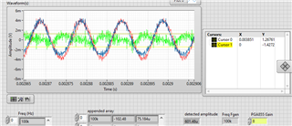
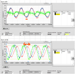
    I repeated the measurement following your parameters, ±15V, 20Vpp sine wave, 0V offset.

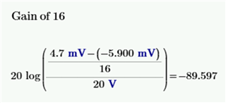
    Gain of 16: 

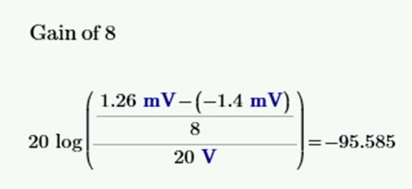
    Gain of 8: 

    So -90dB vs -102dB.

    But if I calculate the ratio based on the (rough) peak to peak value of the screen, I would get

    Which makes more sense...

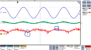
    I do believe your G=8x result should be better, since there was some kind of switching noise captured also: 

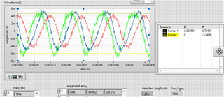
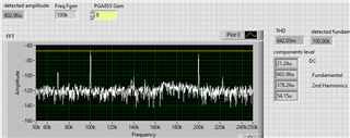
    I looked more closely at my waveforms, and the Gain of 8 waveform looks quite distorted. I ran a harmonic analysis, and got this: 

    The 2nd harmonics is quite significant, and thus the THD is >60%. My characterization was using only the fundamental value for CMRR, which in this G=8x case gives a better number.

    So my first question would be: in this case, how would TI characterize the CMRR, given that the harmonics are quite profound?

    I also notice, the OUT+ and OUT- behave differently at different gains.
     

    At G=8x, OUT+ and OUT- are essentially in phase, so the rejection is very good.

    At G=16x, they are out of phase quite significantly, causing the CMRR to degrade. Since they are subjected to the same input signals, can TI share some insights on this behavior?

  • Hao,

    The CMRR is a measure of the amplifier's ability to reject common-mode input signals. Therefore, instrumentation amplifiers are not expected to provide clean sinusoidal signals results free of distortion when only applying common-mode input signals (no differential signal); where the CMRR test is actually measuring an error signal. The CMRR output measurement is an error residual signal due to small mismatches of the internal precision gain resistor network and internal amplifiers.

    On the test above, a very large 20Vpeak-to-peak input common-mode signal at 100kHz is applied, while placing the gain of the amplifier on a G=16x, and measuring a residual output error signal in the few millivolts. This would be a very large common-mode input signal condition in a real world application.  At G=8x you are getting results that are right on target on the typical spec at 96-dB; and at G=16x you are about ~6-dB from typical. Keep in mind, some variation is expected on the CMRR from device-to-device.  To put things into perspective, if you look at the DC to 60Hz CMRR spec on page 5 at G=16x, typical CMRR is 124dB, but the minimum specified spec is 106dB; where CMRR can vary up to ~18dB. These specifications are comparable (or better)  than other programmable gain amplifiers in the same class as the PGA855.

    Best Regards,

    Luis   

  • Thank you Hao,

    Kind Regards,

    Luis