This thread has been locked.

If you have a related question, please click the "Ask a related question" button in the top right corner. The newly created question will be automatically linked to this question.

INA700: INA700 output current versus Alert pin

Part Number: INA700


Hi Team

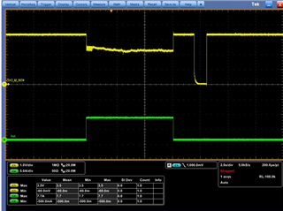
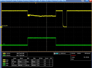
below picture is  INA700 for Iout over 7.3 A  application.

I have two question below:

1. is it retry when I out over 7.3A? if yes why INA700 retry here.

2. why Alert drop after Iout disappear.

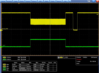
here is Zoom in for INA700 Alert pin.

currently . they don't have any I2C connection.

BRs

Brian

  • Hey Brian,

    I will send my respond shortly. 

    Best,

    Peter

  • Hey Brian,

    Can customer retry the test, but with ALERT pulled up to VS with a 10 kOhm?

    What is the over-current ALERT threshold set to?

    Sincerely,

    Peter

  • Hi Peter

    1. ok  I will let my customer side try it.

    2. they don't connect any I2C connection now. do INA700 have any default overcurrent protection?

    BRs

    Brian

  • hi Peter

    please refer below result for change the pull resistor to 10k.

    BRs

    Brian

  • Hey Brian,

    My apologies for the delay. There are no default over current conditions. All of the over and under condition registers are set to maximum or minimum respectively. Maybe you could be triggering the bus under voltage (so VBUS going below 0V). You could check this by reading bit 3 of the ALERT_DIAG register. You may want to repeat test and capture simultaneous waveforms of VS, VBUS, and V_IS+ so we can have a more complete understanding of the circuit.

    However, I think another potential reason is that you are setting your address pin (A0) to SDA, but yet SDA and SCL are not connected to an I2C bus. In order to the device to know A0=SDA, there needs to be an actual START signal at SCL and SDA. If A0 was set to VS or GND, then you may be able to test device without SCL/SDA connected because, but this becomes irrelevant because you will need to communicate with device anyway.

    I recommend the following steps:

    1. First repeat the same test, but please probe VS, VBUS, and V_IS+ to get a better understanding of environment when the load is turned on. 

    2. Pull up SDA and SCL to VS (or whatever I2C bus level you have) with appropriate resistances (~4.7kΩ typically), then repeat test.

    3. Then connect SDA and SCL to an actual I2C bus with a host processor and repeat test. Read bits 7 to 3 of the ALERT_DIAG register (Bh) to see if any of them are 1, which would mean that corresponding bits condition was exceeded.

    Sincerely,

    Peter

  • Hi Peter 

    below is waveform of remove R674 and R643 change to 10k.

    BRs

    Brian

  • Hey Brian,

    Would debug engineer please attempt the recommendations I sent in last post?

    Best,

    Peter

  • Hey Brian,

    Since we have not heard back from you, I will mark this post as resolved. However, if you have any other updates or questions you can simply reply back or start a new post. 

    Sincerely,

    Peter