This thread has been locked.

If you have a related question, please click the "Ask a related question" button in the top right corner. The newly created question will be automatically linked to this question.

INA180: Measuring DC current to get a sine wave output

Part Number: INA180
Other Parts Discussed in Thread: TPS62933

Hi,

I would like to measure the DCDC buck Iout. The DCDC chip TPS62933 is operating correctly: stable Vout=12V, clean PWM signal, temperature is OK. I'm using E-load to draw stable 1A, 2A and 3A output current from DCDC. 

As suggested in another thread, I should place the current sensing resistor after output capacitors. However, the current sensor output is still a sine wave, also wrong amplitute. 

Please help, thank you very much. 

500kHz PWM SW signal:

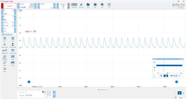
When Iout = 1A, current snesor output is: 

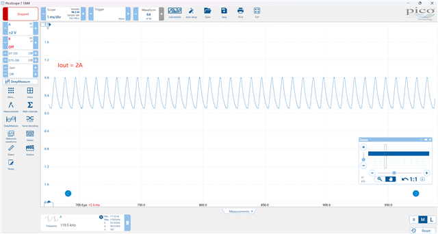
When Iout = 2A, current snesor output is: 

When Iout = 3A, current snesor output is: 

  • Hello,

    Can you rerun your test and remove C14, the output capacitor for the INA180A3?

    Also the input filter you are using may be causing some issues as well. Can you try removing C17?

    Best Regards, 

    Joe

  • Hi Joe,

    Thanks for support. After removing C14, the current sensor output becomes normal DC voltage. But why?

    With/without C17 has no much difference, which is expected. 

    The wrong amplitude is caused by wrong PN the current sensor. I thought the PN is 100V/V, but it's actually 20V/V. 

    Thanks

  • Hi Steven, 

    The thing I noticed about the output was that the DC common mode voltage of the output was changing with different current levels. This told me that the capacitor on the output was limiting the charge and discharge rate of the output signal.

    Whenever you need to have a faster output response, I would recommend removing the output capacitor. 

    I hope this makes sense and I will not mark this as TI thinks resolved. Please respond to this thread if you have further questions. 

    Best Regards, 

    Joe