This thread has been locked.

If you have a related question, please click the "Ask a related question" button in the top right corner. The newly created question will be automatically linked to this question.

Op-Amp circuit design help needed - unity gain and max 4 V output power

Other Parts Discussed in Thread: OPA350, OPA725, TLE2072, THS4062

Hi,


I would like to design an additive op-amp circuit with two voltages, one gained by 1 and the other gained by 3. The supply voltages dont matter, I have anything.

The input voltages are AC 1Vpp that should be AC 3Vpp at the output (gain 3) and an additiv bias that should be gained with unity gain to -1.8V.

The frequency behaviour should be quite linear up to some MHz. The cutoff frequency can be around 10 KHz, or much higher, this doesnt matter.

I've looked in some datasheets (OPA 600 for example) but I could find the right OP-Amp so far.

Can anybody tell me which one could fit? sheap ones ore expensive ones  - doesnt matter, they just should be available somehow.


Kind Regards,

Hendrik

  • Hendrik,

    Perhaps you could provide some more detail so that we can offer some advice:

    What do you mean by "some MHz?"  Can you provide a number?

    You apparently have a circuit topology in mind. Could you please provide a schematic? This would help us to understand your description of the desired circuit function.

    The second signal at unity gain... is it DC or AC?  If you could provide drawings of the desired waveforms it would help.

    Regards, Bruce.

  • Hello,

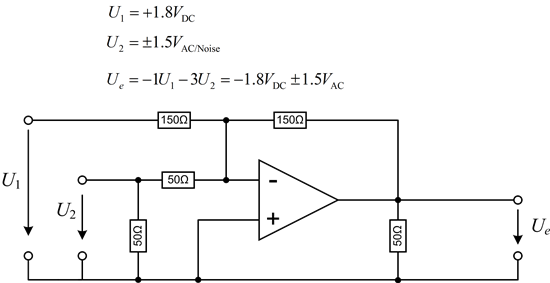
    This is my circuit scheme:

    The U2 Signal is kind of noise-signal (Arbitrary Waveform) and has a in the spectrum a 3dB cut off frequency around 5kHz. Therefore, it is sufficient if the OP-Amp can drive frequencies within the Signal up so some Mhz. Lets say 10 MHz cuf off of the OP-amp is sufficient.

    The second signal at unity gain is DC, yes.

    What kind of OP-Amp would you suggest?

    Kind regards,

    Hendrik


  • Hendrik;

    With your noise source rolling off at such a low frequency (5kHz), there seems to be no reason why the resistors are so low. I'd scale the resistors up by a factor of 100, use an OPA350 operated on +/-2.5V.

    Unless there is some need for impedance matching to an external signal generator, rempve the 50 ohm resistor from the op amp output to ground and from the U2 input to ground. This will not affect the signal gain, only the severe loading caused by the low resistance. If the frequencies were well into the MHz region there would be good reason to keep impedances low but that is not the case here.

  • I just noticed the output voltage requirement-- make that an OPA725 operating on +/-5 or 6V.

  • Hello Neil,

    thank you very much for your answer! Do you know how long "samples" of the OPA725 would take to deliver? (germany)

    so you would suggest to use 5kohm and 15Kohm instead for the gain adjustment, ok.

    Further: Im connecting U2 with SMA-Cables, these need to be terminated with 50Ohm, so I would then still need these for impedance matching to an external signal generator. So the two 50Ohm impedances to ground are then still right, isnt it?

    Kind regards,

    Hendrik


  • Hendrik;

    Samples from TI are usually shipped very quickly.

    At the low frequencies that you are using,, impedance matching coax cables by terminating them in their characteristic impedance is completely necessary.

  • Hello,

    I looked in the Specs Scheets and:

    I need DIP (Dual in Line Package) with 2.54mm spacings of the contacts. The mentioned OPA725 would fit the requirements, however, I would need a DIP Package, which doesnt seem to be available for the OPA725.

    What would you suggest? Which other OP-Amp might fit then?


    Regards,

    Hendrik

  • Hendrik;

    You could use the precision OPA227P on +/-12V or +/-15V supplies. It is in a DIP package.

    Most new op amps are being introduced in surface-mount packages only; there is so little demand for DIP packages that it is not worthwhile for IC manufacturers. There are tiny adapters made to convert surface-mount devices to other footprints-- including DIP-- so those may be an option for you. These adapters are available from major distributors.

  • Hello,


    Thank you for your answer. The OPA227P is not available for free samples.

    Another problem is that the OP has to be unity stalbe and has to be able to provite 40mA. Most of the OP-Amps provide only a short-circuit current of 40mA and would then lead to distortions by operating with 40mA.

    However, the TLE2072 is in P available for free samples and could provide +-45mA. Would this be sufficient for distoriotn less operation with 40mA needed output current?

    Futher, the OPA551P could provide 200mA, but isnt available as free stock as well. The ideal OP-Amp would be the THS4062 i think. But:
     Nor available for free samples.

    How does it work if there are no free samples availaible?

    Are there on the market adapters from D Socket do DIP sockets? `How are they called?


    Regards,

    Hendrik