This thread has been locked.

If you have a related question, please click the "Ask a related question" button in the top right corner. The newly created question will be automatically linked to this question.

opamp for analog output in a car module

Other Parts Discussed in Thread: OPA171, OPA1641, OPA827, OPA209, OPA134

Hi,

I'm searching for an opamp which can drive an analog output on a pcb for a car module.
maybe the OPA171 can do the job.
I need 0-5V, 10mA. I Will give the opamp a 7Volt sapperated supply.

But the problem is SHORTS to +12V and to GND.  To GND seems no problem. but to 12V it is.
I can not find/read any datsheet information about this.

I'm thinking about a 7Volt supply with a series diode in it, so the extrernal 12V on the output may
lift the supply up to 12 Volt. (even 18V is needed). What will the opamp do?  try to short the 12V to gnd
with it's output stage?  Does it have thermal protection?

Marien

  • Hi Marien,

    In all cases you want to avoid applying a voltage level on the output pin that is higher than the operational amplifier supply level. The result of doing so may be disastrous. The output pin of a modern operational amplifier leads back to the collectors, or drains, or some other output transistor configuration and an ESD cell. What it consists of is dependent on the amplifier's design and intended use. But no matter what it consists of shorting that output to a higher positive level will likely result in internal semiconductor structures being biased in unintended manners. That can set up high current flow, or internal breakdown, leading to amplifier damage. Many operational amplifiers are thermally protected, but that won't offer an protection against unintended bias conditions.

    The short to ground is a different situation because the ground potential is within the range of the two supply rails. Often, the output device that sources current to the ground has built-in current limiting keeping current limited at a safe level.

    Regards, Thomas

    PA - Linear Applications Engineering

  • Marien,

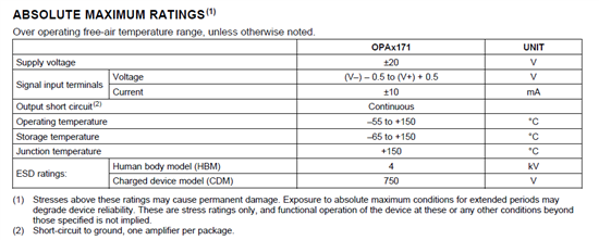
    OPA171 work off supplies from 0V to 2.7V (+/-1.35V) up to 36V (+/-18V) - see PDS table below.   I am not sure what you mean by "shorts to 12V" but if you refer to supply voltage, OPA171 will work just fine being power directly by 12V or 7V so there is no need for any diodes in series with power supply (or battery).

    As far as your last paragraph is concern, I am not sure from your description what your circuit configuration looks like - I will need you to draw the circuit if you need further help; as a side note, diodes in series with the supply voltage cannot "lift the voltage' above supply -  they may only drop the voltage below the supply.

    If your application involves a car audio signal, OPA1641, OPA827, OPA209, or OPA134 are better suited because of their higher speed and lower distortion.

  • Hi Marek and Thomas,

    Thanks for thinking with my issue.

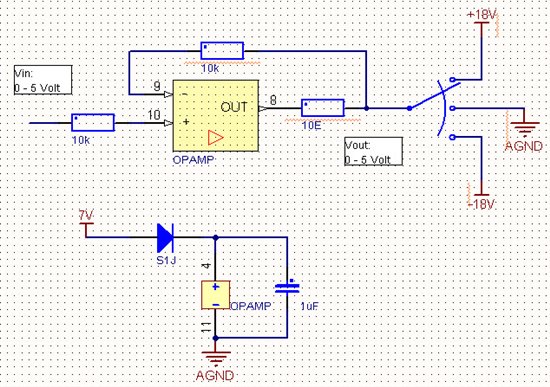
    This is the schematics which basicly explains my circuit. Not very unuses.
    The end application is an car ECU which must make an analog signal similar to a sensor of the engine.

    For signals between 0 - 5 Volt there is no problem, this will work.

    But due to the automotive test specification, I must handle an overload of -18 Volt and +18V.
    During inatallation of a unit the engineer can make a mistake with connecting the wires. This can lead to
    +/-18 Volt connections to the output. The -18V is arbritary, so this one may be skipt.

    My idea was to let the V+ supply of the opamp increase when the putput is connected to 18Volt.
    But I do not expect this will work.
    In case of a 2.5V input voltage. The opamp will sink the 18V source. The opamp goes in thermal shut down?
    And what than?

    Nice application, isn't ? I hope to find a (cheap) solution, otherwise we have to make the systeme less robust.


  • Marien,

    The only way to protect the output from a permanent damage due to accidental short to 18V is to limit the current sunk by the ESD_Vdd_Vout protection diode (see the OPA171 ESD protection schematic below).  As the output is taken above the positive (+7V) rail, the ESD_Vdd_Vout diode gets turned-on and shunts the current to a negative rail. No op amp, however, is designed to have their output driven more than a diode above its rail by an external voltage source and applying 11V above its rails (18V-7V) will result in 11V forward biasing of p-n junction of the ESD diodes - without limiting the current through ESD diode such condition will result in a catastrophic damage of the output stage. as this would result in huge current flow through thin internal  IC metal traces.


    We specify the maximum input current to 10mA at the input terminals - see table below - in case of forward-biasing of the input ESD protection diodes while pulling the inputs above or below the supplies, and therefore the same 10mA max current must be assured in the case of pulling the output beyond its rails as seems to be the case in your application.  The simplest way to limit the current at the output terminal to prevent damaging the op amp output would be to place a 1.8k resistor in series with the output terminal or if possible to limit the max supply current coming from +18V external supply.

  • Hi,  thanks again for the ideas and information,

    I miss the item that I may lift my opamp supply voltage. (the serie diode).
    So when the output gets 18V, via the ESD diode the supply voltage may rise to 17.5 Volt. As long as the
    opamp voltage can handle this, and the total currunt stays <10mA.
    Opamps for upto 36V are no problem.

    I expect that the opamp wil try to sink the current, with its transistor between output and GND. Until this one
    goes thermal down, then the voltage increases upto 17.5Volt.

    Still I don't expect any (cheap) opamp can do this.

    So I thing I gone think about a serie protection in the output wiring. A switch or something like that.

    Marien