This thread has been locked.

If you have a related question, please click the "Ask a related question" button in the top right corner. The newly created question will be automatically linked to this question.

TL103W: Implement isopower characteristic to be added on CV/CC controller

Part Number: TL103W
Other Parts Discussed in Thread: TL431

Tool/software:

Hello TI expert,

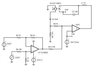
I'm writing since I'm wondering if there's a way to play around the classical CV/CC feedback loop done either by indipendent op-amp or integrated device with reference like TL103W, to get an output current inversely proportional to voltage. I'm not thinking about battery application but more specifically about BLDC motor driving. 

Any idea or application in which something similar has been realized in analog way? In SLLA619 I've seen two current level stepping in depending on output voltage, but such an approach wouldn't work on motor load since voltage is not imposed from the load. I'm thinking to add another feedback loop done by an opamp that act on votlage reference but I'm struggling to get to the proper idea.

any suggestion?

thank you very much 

Gian

  • Hello Gian,

    output current inversely proportional to voltage

    Do you want a constant power regulation? I see this as I = P/V or P = IV ; how much power and compliance range for V and I?

  • Hello Ron,

    Yes a CP regulation could do trick with an xy=cost, but even an output V-I characteristic with "trapezoidal" shape.

    For instance a 30V up to 5A that is linearly reduce down to 20V with a fixed current limit of 20-25Amp.

    I'm thinking to measure and amplifying the shunt current voltage and then driving it into the TL431 voltage reference of the voltage loop. 

    the target at the end of the day is to limit the maximum power having a 25Amp capability at 18-20V minimum. 

    Thank you for your support,

    Gian 

  • Gian,

    That will be easy to implement. The voltage loop is normal.

    For the current limit loop, add current sense voltage and output voltage in the right proportions. Now I limit is modulated by output voltage. You have two choices for output voltage samples, use the live output voltage or the desired programmed output voltage. In former case, current increases as output falls (something needs to be added to make sure current doesn't increase further as Vout drops below 20V). In later case current does not increase as output voltage falls. 

    The later is easier to implement. 

  • Dear Ron,

    Ok for the first part, I could sum the shunt voltage and the output voltage in the right proportion to get I_limit, By the way the second part is a bit difficult for me.

    If I use I_limit as current reference on the E/A of the CC loop, I_limit is increasing while output current demand is increasing.

    At a certain point current shunt voltage let the CC regulation kicks in reducing Vout. Probably I missed something, 

    In the end the CC loop reduces the output voltage, but doing so how to limit the minimum output voltage and the maximum current?

    I think I'm off the road...

    Thank you for your help.

    Gian


  • Gian,

    Using actual Vout [0to 30V] to modify I limit as 25A from 0V to 20V then drop linearly to 5A at 30V, see below.

    U1 subtracts about (20V-VSET) from VOUT and reduces gain. Because U1 can't output below ground, the CC limit is same from 0V to 20V

  • Function result I limit vs Vout