This thread has been locked.

If you have a related question, please click the "Ask a related question" button in the top right corner. The newly created question will be automatically linked to this question.

OPA817: Optimized feedback and gain resistors for gain = 1.1 and gain = 3.3

Part Number: OPA817
Other Parts Discussed in Thread: THS4541, OPA837

Tool/software:

Hello TI experts,

my design includes two OPA817 with a gain of 1.1 and 3.3. Are there some recommandation from TI for the "best" feedback resistor values in case of

- current consumption,

- roubustness (minimazing change of oscillation) and

- noise (as the values of Rf has an influence to the noise)


For example you recommandation for the THS4541 is Rf = 402 Ohm.


Thanks and best regards,

Andreas

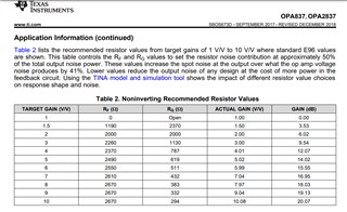
  • Hey Andreas, your question sparked some dim memories of working this issue back in the OPA837 days. This table was noise driven, but with the much faster OPA817, you need to fold in loop phase shift concerns as well back to the 2.9pF input Ccm. I know I built up a suite of calculators for this kind of thing, have not found them yet - but it is a very good and useful thing to think about. Not sure why this kind of table is not in the OPA817 datasheet. _ I will keep looking for the excel calculators for this kind of question. 

    And actually I did find one phase margin centric flow, for your 1.5V?V it calculates Rg = 176ohm so Rf = 88ohms - kind of heavy loading and I might be making a mistake but you could try those in sim and see if the flatness is there - this was targeting an added 15deg loop phase shift due to Rf||Rg back to the 2.9pF input Ccm. 

    The OPA817 Aol sim shows 390MHz GBP - that is what I was using here

  • Hello Michael,

    thanks for your feedback. In fact a compareable table of your provided one for the OPA837 would be nice in the OPA817 datasheet.

    Yes, the load is quite heavy and I will do some simulations. Do you have a SPICE model of the OPA817? 
    At you webpage OPA817 data sheet, product information and support | TI.com a SPICE model is not available,
    also PSPICE for TI version 23.1-2024-S001 does not include a model.

    Best regards,

    Andreas

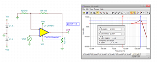
  • Ok, I did find my 2015 full R solution flows and added in the OPA817 parameters, even with these low values at gain of 1.5 it is peaking due to the relatively high Ccm, so you can scale down from here if you don't like the peaking - yes, these are low but the Icc on the device itself is very high

    This file, OPA817 non-inverting gain.TSC

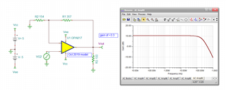
    And then for gain of 3.3, here is what I get, looks real good here, 

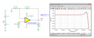
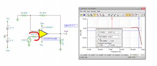
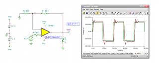
  • hey Andreas - I just noticed you wanted gain of 1.1 not 1.5. Here that is, still peaking maybe more than you want - this is not the feedback pole to the 2.9pF Ccm but maybe just the native low gain peaking of the Aol phase margin, 

    Could perhaps equalize that with a series input R setting a real pole at 500MHz into the 2.9pF on the V+ input as well, pretty good looking 560MHz F-3dB

    The pulse response will not be perfect, but here is a just under slew limited fast input edge 0.5V step size input at .1nsec edge rate at 50MHz. Increasing that series input R might improve this, 

     4237.OPA817 non-inverting gain.TSC