This thread has been locked.

If you have a related question, please click the "Ask a related question" button in the top right corner. The newly created question will be automatically linked to this question.

INA241A: INA240 BCI Test Problem

Part Number: INA241A
Other Parts Discussed in Thread: INA240

Tool/software:

Hello everyone,

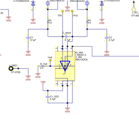
In my project, I am driving valves so that I am using INA240 to read current sense on my custom board. You can see my INA240 design below.

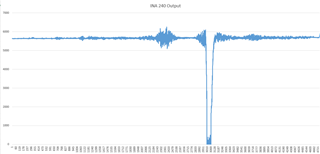
I am doing BCI test on my board (100mA, 0-400 kHz). I set my PWM output to constant 400mA. I expect till BCI test PWM output will stay 400mA. When I check the PWM output and INA 240 Output datas after the test, I saw that there is a problem reading current while BCI test. As you can see below my PWM output is working fine while there is not a problem on INA 240 Output. 

I tried a few changes and tested my board again but the problem did not solve. Can you help me about this problem? Is my design wrong or am I missing some important points?

  

Best Regards,

Basri KAYA

  • Hi,

    There appears to be certain correlation between PWM and INA output.

    Can you connect REF1 pin to VS to see if the behavior improves? Of course, the math will need some adjustment because zero current corresponds to 1.65V with this change.

    Regards

    Guang

  • Hello,

    I think adding offset in my design can not solve my problem. If you think that will help, please explain to me. 

    Should I add input filter in my design like below or only paralel capacitor to shunt resistor ?

    Best Regards.

  • Hi,

    I don’t think adding offset will fix the issue either. I’m curious though if the issue is made worse without it, ie, the output gets stuck at ground for longer than necessary. But regardless, if even a short pulse is not allowed, then there is no need to pursue in this direction.

    The LPF should help and I would keep them. Maybe consider replacing R3/4 with ferrite beads, which should be more effective.

    Regards

    Guang