This thread has been locked.

If you have a related question, please click the "Ask a related question" button in the top right corner. The newly created question will be automatically linked to this question.

INA333: ECG Amplifier using INA333

Part Number: INA333

Tool/software:

Dear Team,

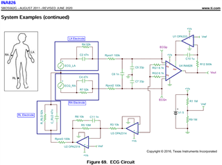
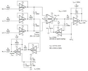
I need to design an ECG amplifier using INA333.

My signal spec is given below.

  • BW = 0.47Hz..40Hz (-3dB)
  • Signal amplitude max. 10mVPV (peak-to-valley), DC offset max ±300mV
  • Sample rate = 256Hz
  • Assume the noise level of the system (referred to input) = 50uVPV (peak-to-valley)

If my understanding is correct the peak voltage of ECG signal is 10mV.I was not able to understand the minimum voltage.

offset voltage is either 300mV or -300mV.This is the common mode voltage I believe.

My amplifier will be working from with 3.3V supply.The final system will be a battery operated one with a max battery voltage of 4.2V.

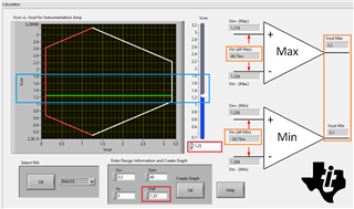
Below is the image from TI calculator.

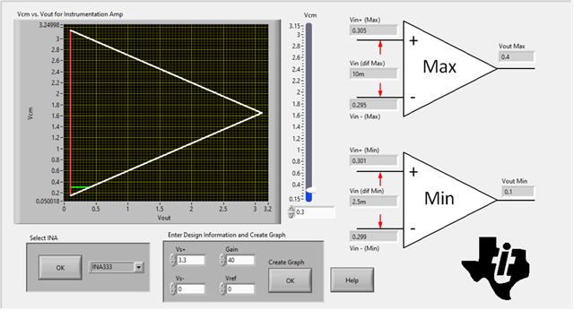
I choose the common mode voltage as 0.3V using the slider

From the above image what I understood is I need to provide a minimum gain of 40 because my maximum signal is 10mV.Please correct me if I am wrong

May I know how to accommodate the offset of -.3V

Regards

  • Hi Hari, 

    Could you share your ECG/EKG schematic or simulation with me? Below is an example from INA826's datasheet. Certainly, you can use INA333 to perform the similar design. 

    Here is INA333's ECG example. 

    If you are using INA333 with 3.3V single supply rail, you would need configure the Vcm in the middle of the unsymmetrical hexogen diagram, where ECG input can swing positive and negative below ground (up to 10mV). The marked orange boxes are the designed differential min and max input range, and INA333's min and max output range is shown on the right of the orange box. I selected Vref = 1.25Vdc for the configuration.

    Enclosed is a related ECG application note that it may help you. 

    https://www.ti.com/lit/an/sbaa160a/sbaa160a.pdf?ts=1717381608112

    https://www.ti.com/lit/an/sbaa185/sbaa185.pdf?ts=1717417559297

    May I know how to accommodate the offset of -.3V

    You may compensate the Vos via Vref signal (Vref = 1.25 +0.3V) or calibrate it out in your ECG/EKG system. 

    Anyway, we can simulate the design requirements once you finalize the basic parameters. Please let me know if you have other questions. 

    Best,

    Raymond

  • Hi Raymond,

    Thank you very much for your time.

    I will go through the documents and will update you tomorrow.

    Regards

    HARI

  • Hi Raymond,

    One more question.

    Different patients the cardiac signal might look different, hence the detection of the cardiac signal should be set based on the signal morphology. How would we overcome this challenge

    Regards

  • Hi Hari,

    How would we overcome this challenge

    Yes, this is challenging part of detection and application.  Your ECG system needs to have this type of fault detections for the measurement system.

    For instance, the ECG electrical probe/pad is typically have conductive adhesives to the patient's skin. I recalled that there are many types of ECG electrodes, such as wet, disposable, reusable, stainless/Ag/AgCl, dry, self-adhesive ECG electrodes etc.. The wet type has conductive gel to interface with patient skin, while dry ECG is using conductive adhesives. In any case, the contact interface is critical for a good electrical contact and measurement. 

    If the measured signals our outside of S/N requirements, then the MCU or fault detection alarm should be activated. This is how to get around the issues. 

    https://www.ti.com/lit/an/sbaa196a/sbaa196a.pdf?ts=1717351833072&ref_url=https%253A%252F%252Fwww.google.com%252F

    If you have additional questions, please let me know. 

    Best,

    Raymond