This thread has been locked.

If you have a related question, please click the "Ask a related question" button in the top right corner. The newly created question will be automatically linked to this question.

OPA990: Not working amplifier

Part Number: OPA990
Other Parts Discussed in Thread: INA169

Tool/software:

Hello. I am designing a current measurement application using a shunt and an amplifier. I selected the OPA990, but i'm testing it and it doesn't work. This is my circuit:
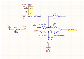
I have a variable voltage at Vin+ (between 4.5V and 50V). I have chosen that shunt because we don't want a big drop voltage at it at max current (2A):

Vdrop = I · R; V = 2 · 0.02; V = 0,04

So i would need a gain of:

G = Vout/Vin; G = 3.3V/0.04 = 82.5

3.3Vout because of my adc reference.

With this, I have followed the next equations.

R1 = R3

R2 = R4

G = R2/R1 = 82000/1000 = 82

I did the following tests.

- First of all, I supplied 3V3 to the OPAM supply rail. Then, i powered the shunt with 5V. Is a high side current  sensor, so I put a power resistor (50R) is series for a little power consumption (I = 5/50 = 0.1A).

- Theoretically, the Vdrop at the shunt will be 2.5mV, so I have to see 2.5 · 82 = 205mV at the output, but I see 3V3.

One of the things I left on my design is the bypass capacitor at VCC/GND, but I think this will not have that big impact in the application.

I have seen in recommened applications bypass capacitors at the inputs of the OPAM, but as the bypass at VCC/GND, I don't think this will have big impact on the design.

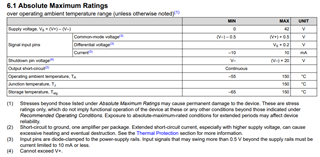
I have checked every parameter on the datasheet, as the common mode voltage, because I'm overpassing the VCC voltage at the inputs, but with 1k at 5V, should be enough (I = 5/1000 = 5mA; datasheet recommends less than 10mA). This is a point to improve for voltages above 10V, but multiplying resistor values by 10 will solve this.

- Then, i mounted an isolated circuit outside the board and I powered the OPAM rail and the circuit with 12V. Could this have damaged the circuit even having 12V in the rails and in the inputs with more than 10mA at the input pins?

Am I leaving something out? Is not my first time designing diferential amplificators, but is using this OPAM and a gain this high (the others amplificators I designed were low gain ones).

I don't know if I could have damaged the OPAM doing any test.

Is a problem to power the OPAM with 3V3 and injecting 50V on the input pins even limiting the current at less than 10mA?

Thanks in advance.

  • The absolute maximum ratings guarantee that the device will not be damaged.
    The recommended operating conditions and VCM guarantee that the device will work correctly.

    Your circuit violates the VCM limit. There are current-sense amplifiers that are designed with common-mode range above VCC.

  • Hi Fran,

    Is a problem to power the OPAM with 3V3 and injecting 50V on the input pins even limiting the current at less than 10mA?
    - Then, i mounted an isolated circuit outside the board and I powered the OPAM rail and the circuit with 12V. Could this have damaged the circuit even having 12V in the rails and in the inputs with more than 10mA at the input pins?

    Clemens once again beat me to it but yes this would be a problem. A lot of people make this same mistake where they think choosing a high voltage device will bypass the input common-mode voltage range. In reality, looking at the absolute maximum ratings table, you can see that the input pins common mode range is dependent on the supply voltages. 

    Also 50V violates even the supply voltages absolute maximum rating. 

    Clemens suggestion of current-sense amplifiers is likely the best solution. You could also use a difference amplifier. 

    Best Regards,

    Robert Clifton 

  • Thanks for the response. I selected the INA169 and probably i will be using it with an OPAM at the output as a buffer.

    But this is messing me, because right now, I am not powering it with more than 10V and I am not getting the value I want at the output, neither anything close to it.

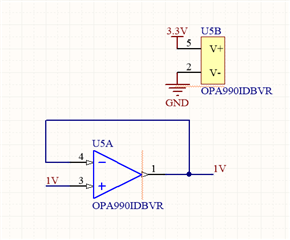
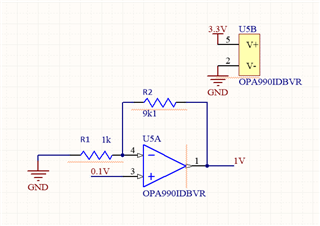
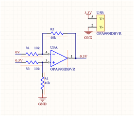
    I have tested the OPAM as a voltage follower and as a non-inverting gain x10 for testing if the OPAM was broken, powering it with 3.3V and injecting in the first case 1V and getting 1V in the output, and injecting 0.1V in the second case and getting 1V at the output. But then, I configure it as a differential amplifier gain x4, powering the rails with 3.3V and injecting a differential voltage of 0.3V but not above 3.3V single pin voltage, connecting to the positive input of the OPAM the higher potential, and i'm getting 0.3V at the output. I tried also with gain x10 but anything different happens.

  • Thanks for the response. If you could help me with what I replied to Clemens I would appreciate it.

  • Please show the schematic, and the voltages you are measuring at the three I/O pins.

  • Yes of course.

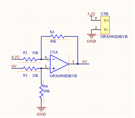
    I tested these three configurations.

    I am injecting the input voltaje at the OPAM with a laboratory power supply connected to the board GND.

    Voltage follower: i tested input values from 1V to 3V and everything ok.

    Non-inverter: I tested input values from 0.1V to 0.2V and everything ok.

    Differential

    I also tried the differential swaping the input pins but the output is 0.

    I'm measuring the output with a Fluke 115 multimeter.

  • In the "differential" circuit, the output voltage does not make sense. Please provide the voltages at the input pins, and check that no resistors were exchanged.

    In the "differential swapped" circuit, you are asking the opamp to generate an output voltage below its negative power supply; this is not possible.