This thread has been locked.

If you have a related question, please click the "Ask a related question" button in the top right corner. The newly created question will be automatically linked to this question.

INA116 Problems

Other Parts Discussed in Thread: INA116

Hi,

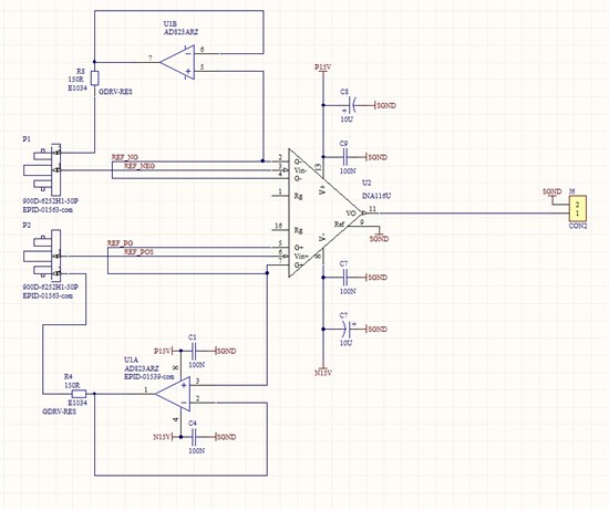
I have tried to use a INA116 Instrumentation amp as part of a potentiostat. I wanted to use the amplifier with a gain of 1 to provide a HIZ differential amp to measure voltage on a pair of electrodes. I wanted the ampl to have the capacity to take a +/-10V signal at 10Khz BW or so.

I have a pwr supply of +/-15V and am using a pair of opamps as per the app note to drive the input guards.

The ccts works well at DC, The guard ccts work well and impedance is indeed high.

My probelm is to do with distortion of the output at higher frq. The data sheet seems to indicat that the amp should work with a 10V output at more than 10K when on a gain of 1.

In practice however, I see a large amount of distortion when driving the input with a 10V pk sine at 10khz. The distrotion starts at about 3V pk at 3khz

The guard signals do not have the distortion and this indicates to me that the problem lies in slew rate limits on the instrumentation amp section.

When operating with a gain of 10 and using a 1V pk signal the cct performance is better but this is not good for my application.

Can anyone advise where i am going wrong?

I have tried a different chip on this cct as i thought the first one may have been damaged. so a second one from a different vendor was tried but it had the same results.

Because the guard ccts work i was thinking of using them to drive a external difference amp to get my  output signal but this seams to be a bit silly.
 

  • hi

    This was my first though too.

    The datasheet is a bit vague on this point. The spec indicates slew rate of 0.8V/uv with gains of 10 to 200 but no data at gain 1.

    Unfortunately the device is not good at values much lower than the expected slew rate limit.

    I have tried driving the amp with a triangle wave of 10V pk-pk at 10kHz and the slew rate in this case is 0.217v/us. Not to fast!

    The distortion on the sine wave is occuring just after the peak not at the fast point.

    Maximum out vs freq indicates that 20 pp at 10 Khz sine but it does not mention  distortion or linearity.

    The scope pics in the data sheet which show small and large signal response show a fairly slow signal and my pcb performs the same as these pics show.

    I cant believe that this is how it is meant to work and i am frightened that i will have to ditch this device in favour of a new design ( arent i lucky i built a prototype!)

    I include a pic  which shows the result. yellow trace is the output and the blue trace is the guard signal ( note the signal follows input, which indicates problems in the output section)

    I am really stumped and am very happy for any suggestions

    Regards