Other Parts Discussed in Thread: AMC3302
Tool/software:
Hi TI Experts,
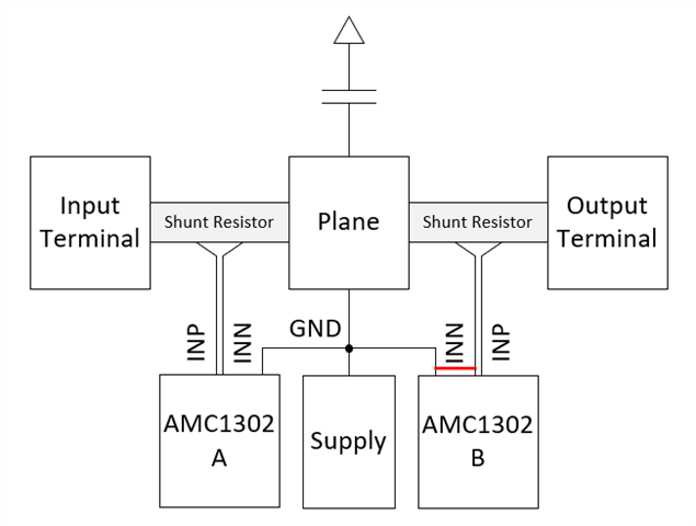
As shown below, I use two AMC1302s to sense the currents before and after a filter capacitor. The common ground is set as the terminal plane of the capacitor voltage.
In the PCB layout, I improperly connected the GND pin and INN pin at the righ-side AMC1302, which created a ground loop.
Consequently, I find there are significant low frequency distortions at the outputs of both AMC1302s.
My questions are:
1) I can understand that the performance of the right-side AMC1302 will be affected by the ground loop. But why the left-side cannot work properly? Is it also because of the right-side ground loop? Due to this issue, I am not sure if the distortions will be suppressed by breaking the additional wire.
2) Will the wire length of INN and INP generate low frequency distortions. In this pcb layout, the wire length of INN and INP is up to 45mm due to the limited space, though the pcb layout is symmetric.
Thanks for your help.