This thread has been locked.

If you have a related question, please click the "Ask a related question" button in the top right corner. The newly created question will be automatically linked to this question.

OPA836: Peak detector based on OPA836

Part Number: OPA836

Tool/software:

Hi everyone,

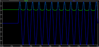
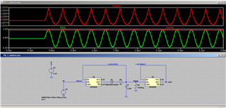
I'm working with the OPA836 and I need to design a peak detector. I'm using the simplest circuit to simulate it, as shown in the following figures.

Some characteristics of the OPA836 for the peak detection circuit:

  • Slew rate = 560V/μs
  • Voffset = ∓65μV

The difference between the figures is just the input voltage offset (since I'm working with a single power supply).

I want to detect signals with a rise time of 50ns, so I used a 5MHz sinusoid to obtain this rise time in 1/4 cycle. At this frequency, Xc1 = 21k.

What's wrong with these circuits? What am I forgetting? This is the simplest peak detector circuit, but I can't get it to work based on the OPA836.

  • Hi Adelson,

    I was not able to recreate the problem you are seeing in simulation; however, one concern is the 100Meg resistor in series with the capacitor. The model does account for Ib which is in the nano-amps. This large resistor will interact with this bias current and is likely what is affecting results here. I would use a value around 100k and adjust the capacitor accordingly. 

    Best Regards,

    Ignacio

  • You mean the 100Meg resistor in parallel with C1, right? What influence would this resistor have on altering the offset of the input signal?

    I've attached the simulation file.

    Thanks

    Sim.zip

  • Hi Adelson,

    Yes, the 100Meg in parallel. Could you explain what you mean about altering the offset of the input signal? The concern with this resistor is the input bias current interaction which would affect the bias voltage of the circuit. Unfortunately, I was unable to open your files as we are not licensed to use LTSpice.

    Best regards,

    Ignacio