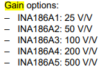
This thread has been locked.

If you have a related question, please click the "Ask a related question" button in the top right corner. The newly created question will be automatically linked to this question.

INA186: Pressure Transducer Current Loop Receiver Questions

Part Number: INA186
Other Parts Discussed in Thread: RCV420

Tool/software:

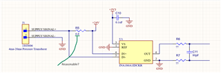
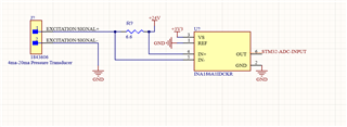
I'm designing a 4ma-20ma current loop receiver for use by an STM32F765BG MCU. The MCU accepts 0-3V3 for measurement.

This is for an industrial PCB. I have chosen the INA186 over the RCV420 to avoid voltage drift due to temperature.

I want to ensure that my schematic is correct, and in addition, if I could have help in preventing EMI issues from nearby A/C (480v 3-phase or 120v single-phase 60hz). To clarify, this board is powered off of a +24VDC supply, but A/C may exist inside the same enclosure.

Should I be filtering the input/output, adding fuses, diodes, etc? Or is this handled by the INA186 IC?

Thanks!

  • Hello Jeremy, 

    Thank you for your post. 

    Typically for EMI, we recommend placing a ferrite bead on the signal trace that would be susceptible to the noise. 

    I do not see a bypass capacitor on your supply which we do recommend 0.1uF. Please also adhere to the layout recommendations below:

    If you expect your inputs to be noisy, you can consider implementing the CF and 2X RF filter shown above. 

    Please also take a look at Current Shunt Amplifier Considerations for Driving SAR ADCs if the output of the INA186 is driving a SAR ADC.

    If so, you may have to implement a charge bucket filter like the one from the considerations app note:

    I hope this helps, 

    Joe

  • The ADC for this MCU does happen to be a SAR ADC.

    For the charge bucket filter, I have calculated C_FILT to be 80pF

    - The typical value for sample and hold capacitor for the ADC is 4pF. 20*4pF = 80pF

    I am having trouble calculating R_FILT, I'm not sure how I can determine T_OA to determine T_RC and calculate R_FILT.

    ------

    My understanding of current sources were that they were very resistive to noise, so I'm not sure if it would make sense to put a ferrite bead on the signal trace. However, I'm a first timer here so if you have any thoughts on this they would be much appreciated.

    Really hoping to have this work first try. Are there any free simulation tools available?

    Thanks Joe!

    Edit: Here is the current, updated schematic with the addition of the bypass capacitor and charge bucket filter with unknown R_FILT/2 values.

    I ask the question of whether or not the resistor value is reasonable or not since the spec is <= 1kOhm. This seems very low for the intended application. Perhaps something else would be better suited?

  • Hi Jeremy, 

    You can use this online calculator to find the best values for the R_FILT: ANALOG-ENGINEER-CALC Calculation tool | TI.com

    The theory behind the tool is in section 3.2 as you may have already gone through.

    In terms of the sizing of your sense resistor, I would need to know your sensitivity option that you are using and your range of input currents:

    You want the output to be within the 3.3V supply rails. So long as you're happy with the range of outputs, I would say it is okay to use. 

    For EMI,

    We usually recommend using a LPF for frequencies of noise below 100MHz and for anything higher is when it is appropriate to use a ferrite bead. The best approach would be to probe the system before using the amplifier to see if there is in fact noise being generated. Then you could implement one of the above recommendations. 

    I hope that makes sense. 

    Best Regards, 

    Joe