This thread has been locked.

If you have a related question, please click the "Ask a related question" button in the top right corner. The newly created question will be automatically linked to this question.

INA826: Vout range from simulation doesn't match actual

Part Number: INA826

Tool/software:

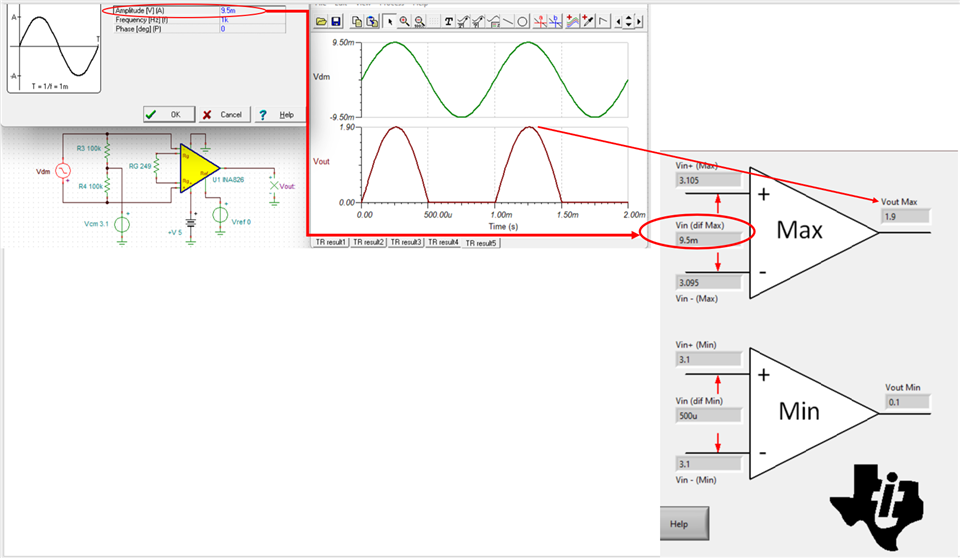
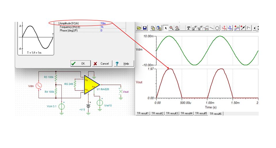
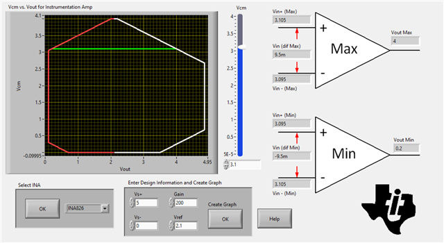
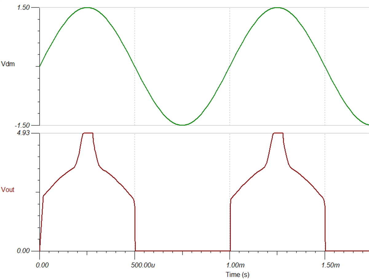
Hi, I'm using the INA826 to amplify a wheatstone bridge pressure sensor where the measured IN+ and IN- voltages are both ~3.1V with no pressure applied. Vs+ = 5V, Vs- = 0V, Vref=0V and gain=200. Using the simulator, the Vout range is given as 0.1V-1.9V but when I test it out, Vout increases to ~3.6V with applied pressure but cannot increase past that. What is the reason behind this discrepancy? And how can I get it to maximise the Vout range?

Thanks!

  • Hi Iris,

    I have simulated the circuit and the calculator and simulation align. The calculator shows the max input differential signal that can be applied to operate within the linear operating range of the device is 9.5mV. I simulated with a differential voltage of 9.6 mV and the output maximum linear voltage is 1.9V as shown below. 

    Taking the input differential signal higher than this results in distortion of the signal and is outside of the linear operating range in this configuration. Below you can see output waveform distortion when the input is violated. Going beyond the linear max input differential input will result in unexpected results. 

    I need to restart my computer and will follow up with adjustments in the calculator. Below is my Tina simulation.

    Best Regards, 

    Chris Featherstone

    INA826 Config.TSC

  • Hi Iris, 

    To follow up you may consider adjusting Vref to 2.1 V as shown below in order to increase the linear operating output to 4V. In addition this allows for a minimum input differential voltage to be extended down to -9.5 mV from 500 uV. 

    Best Regards, 

    Chris Featherstone

  • Hi Chris,

    Thanks for your response. Beyond the linear operating range, what behaviour can I expect? I measured the differential voltage to be 18mV (with no pressure applied) and Vout was around 600mV. Vout changed with applied pressure up to 3.6V and saturated there. I've attached the schematic for reference. Thank you, appreciate your help.

    Iris

  • Hi Iris, 

    When exceeding the linear operating range I wouldn't expect the circuit to behave as expected. The input voltage can even go as far as past the power supplies however linear operation will not be observed and the input protection circuitry will be activated. This makes it difficult to know what the expected behavior of the device will be in the non-linear region. 

    I can violate the linear operating range as shown below. However this behavior isn't predictable and may vary in the real measurement. 

    The RG resistor should be placed as close to the RG pins of the device as possible to minimize parasitic capacitance that can cause instability. 

    Best Regards, 

    Chris Featherstone