This thread has been locked.

If you have a related question, please click the "Ask a related question" button in the top right corner. The newly created question will be automatically linked to this question.

OPA357: Charge amplifier design

Other Parts Discussed in Thread: OPA357, LMH34400, TINA-TI

Tool/software:

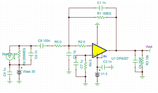
I would like to design a charge amplifier for a sensor with 1nF and 200MOhms and bias voltage 30V. Sensor current is around 1 mA. This is the circuit I have now:

My output is a strange:

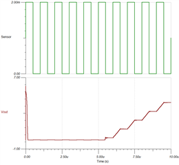
I have tested several parameters to get a better output, but without success. Any suggestion on how to improve this?

CSA-SiPM-OPA357.tsc

  • By the way, is this a good amp op for this application?

  • Hello Daniel,

    Myself and the HSAMPS team are going to work on this for you, I do apologize for not having a response to you earlier.  We had a mix of project priority changes and team members out-of-office.

    To help clarify and understand, are you using the OPA357 as a transimpedance amplifier (TIA) for a SiPM (silicon photo multiplier)?

    We do have our OPA85x discrete family of TIAs, as well as our integrated TIAs (LMH3240x & LMH34400) for optical applications.  The OPA357 may be adequate here too, but I wanted to give you some ideas while we work on a solution.

    Best,

    Alec

  • Dear Alec,

    Thank you for your reply. I would to use the OPA357 as a charge amplifier for a SiPM. It is not a TIA. I checked the op amps you mentioned, but the consume a lot of current. Does the current source I used is a good representation of a SiPM?

  • Hello Daniel,

    Thank you for clarifying.  Let me check with my team on part recommendations (or keeping OPA357) as well as how to model a SiPM.

    I will update you tomorrow.

    Best,

    Alec

  • Hello Daniel,

    Do you know if you will be using the fast output of the SiPM, which is a voltage signal, or the current output of the SiPM for your design?

    Best,

    Alec

  • Dear Alec,

    We will use the current output of the SiPM. Thanks!

  • Hello Daniel,

    I overlooked an aspect of your circuit in my previous messages.  With a feedback resistor setting the transimpedance gain of 1MOhm (one megaOhm), your current of 10mA would result in a voltage of 2kV (two kilovolts)!!

    This will not work and will certainly result in a broken amplifier.  I think reviewing your SiPM datasheet and adjusting to a smaller Rf resistor and Cf capacitor would help your design.

    Please let me know if you need further support.

    Best,

    Alec

  • But this should be a charge amplifier, not a transimpedance. How should I correct the circuit to operate as a charge amplifier?

  • Hello Daniel, 

    What voltage signal output do you need from the charge amplifier?

    I can help understand what to change.  Are you modeling the SiPM and it's output pulse correctly in simulation?

    Best,

    Alec

  • It could be 1V.

  • Hi Daniel, I was following your post hoping to learn what TI colleagues think of your choice of the opamp. It is a pity that Alec was busy, but perhaps I could get us a tiny bit closer to the solution. 
    The amp will not result in a 2kV signal because your SiPM is AC-coupled to the opamp. This is a charge-sensitive amplifier, not a TIA, and simulation results also make perfect sense. I am not sure about the 5us starting gap; possibly OPA357 is simply not fast enough to integrate sufficient charge and get some meaningful voltage on the capacitor in that period of time, but after that you see a typical integrating ladder. The 1Meg capacitor in a charge-sensitive amplifier is not for converting current into voltage but for discharging the capacitor. There is no current flowing into the opamp because of the coupling capacitor C8. 
    Your schematic is perfectly suitable for measuring the average SiPM signal with some modification. If you add a circuit that resets the capacitor when, for example, Vout reaches 1V, you can continuously measure the charging speed, which would be a good proxy for the average current from your sensor over time.   
    However, if you want to detect light pulses and expect to see a typical CSA signal with an exponential discharge tail, you need to reduce the value of your resistor. Starting with 50k (RC of about 50us) would make sense, but it depends on your objectives and the opamp stability. Alternatively, you can change the duty cycle of your input signal to allow enough time for C8 to discharge through the 1Meg resistor. It will probably take a while...  

    Perhaps together we can take Alec up on his kind offer to build an SiPM model for TINA-TI? That might actually give everyone a better idea regarding which opamp from TI would work best in this application. 

    Anyway, I hope it helps and my apologies, if you spot any flaws in my comments. 

    BR,
    A

  • Dear Alex, thanks for your reply and sharing your thoughts.

    Our idea is to implement a circuit to discharge the capacitor, indeed.

    If the starting gap is just a transient effect, it should not affect the response of the circuit. In fact, a SiPM model for TINA-TI would be very welcome to understand if the OPA357 is a good choice in terms of performance and power consumption.

    Regards,

  • Hello Daniel,

    Would you be able to share your SiPM product information?

    I will work on using your circuit in simulation and suggesting improvements as I discover them.

    Best,

    Alec

  • Daniel, I agree, AFBR-S4N44P014M would be my choice too. If Alec could help with a model for this chip, it would be much appreciated. 
    Regarding OPA357 specifically, my biggest concern is that in your simulation no charge is integrated in the first 5us. It is a big gap... Perhaps it will go away, if you replace R1 with an on/off switch, but in real life a lot will depend on what exactly you will be measuring. If you require sensitivity down to a single photon level, you will probably need a much faster decompensated opamp, which is a challenge in itself. Also, such CSA will be difficult to get right because you will need really serious EMI shielding. Your amplifier will be affected by noise from all possible sources. Just sorting our power for your opamp will be tricky. If you have plenty of light to work with, you might be better off with a TIA and some sort of a peak and hold circuit as Alec suggested in the first place. There might be a sweet spot for a charge sensitive amplifier somewhere in the middle. Let's hope we can learn more with some help from TI.   

  • Hello Daniel, Alex,

    I will take a look at the SiPM and see what I can figure out for modelling and representing the device for our charge amp, TIA, and other circuits.

    Best,

    Alec

  • Hi, Alex. The CSA would be a "nice to have" feature in our circuit, but we will not use it if we have to change the OPA357 to a faster opamp since it will increase the power consumption and we have to face EMI challenges, as you said. Definitely, a SiPM model would help us on this matter.

  • Thank you, Alec!

  • Hello Daniel,

    I have some critical lab work to finish, so I may not get a chance to look at the model until tomorrow or Monday.  I am committing to figuring out a path forward for you.

    Best,

    Alec

  • Alec, here is a detailed SPICE model diagram, which is in good agreement with experimental results. The source is doi.org/.../j.nima.2018.11.118  "Understanding and simulating SiPMs, Fabio Acerbi, Stefan Gundacker. I hope you find it useful. 


  • Hello Alex,

    I appreciate you finding a good resource while I was finishing lab projects.

    I will certainly take a look Slight smile.

    Best,

    Alec