This thread has been locked.

If you have a related question, please click the "Ask a related question" button in the top right corner. The newly created question will be automatically linked to this question.

Charge Sensitive Preamplifier Op-amp Selection

Other Parts Discussed in Thread: OPA191, TINA-TI, LMP7721

I would like to choose an op-amp to design a charge sensitive preamplifier. I'm not sure what op-amp to use for my application. Searching online I have found designs that have used a voltage-feedback op-amp, electrometer op-amp, CMOS op-amp, JFET input op-amp, or an op-amp with an external JFET. I would like to know which configuration of the ones I mentioned would be best to go with or if there is a better one. I would like the charge sensitive preamplifier design to be ultra low noise. My understanding is that the op-amp should have low input current, low leakage current, low input offset voltage, low drift, and low noise.

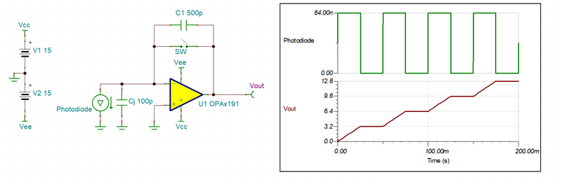
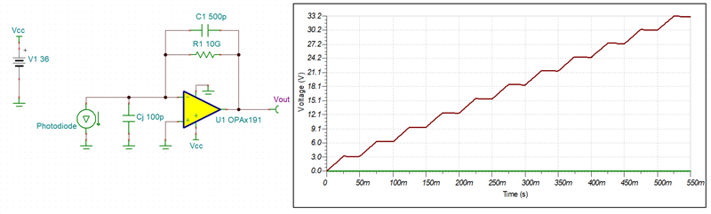
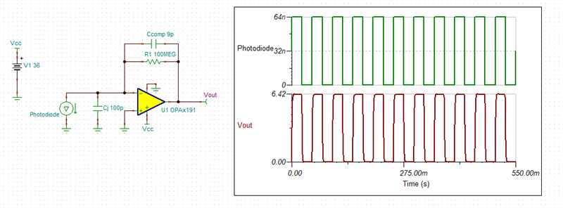
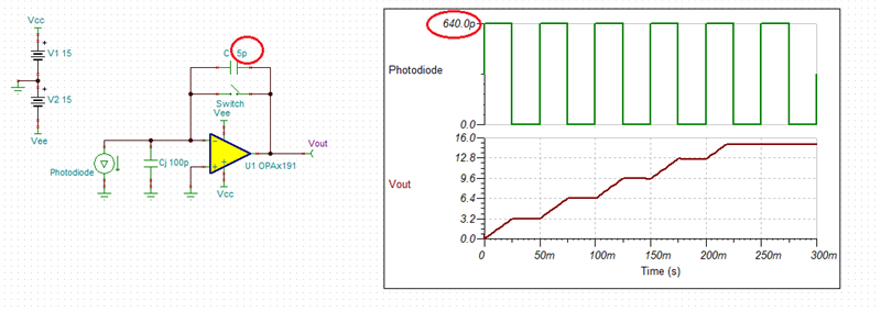
My application uses a photodiode detector. The detector generates about 1E8 electrons per light pulse. The light pulses are at 20 Hz. The detector capacitance is slightly above 100pF. What considerations should I take when choosing an op-amp with a 100pF detector capacitance?
I would like the voltage supply range of the op-amp to be between +/-3V and +/-15V.

Thank you for the help.

  • Steve,

    100 million (1E8) electrons per 20Hz pulse would mean a charge flow of 1.6E-11 coulombs (Q=1.6E-19*1E8) per period of 50ms or average 32nA (I=Q/t). In order to determine the required value of the cap, one must decide the change of the voltage per pulse. A 3.2V increase per pulse would require C=i*t/V = 32nA*50ms/3.2V = 5E-10 or 500pF cap.

    For 50% duty cycle pulses at 20Hz, the output voltage is shown below using OPA191 with dual +/-15V supply.  The SW switch resets the output voltage. 

    One could also use 36V single supply to maximize the output voltage range.  And instead of the switch use a bleed resistor but its value would need to be 10G or higher to minimize error caused by C1||R1 exponential decay - see below.

    Below I have attached Tina-TI schematic for your convenience.

    OPA191 Charge Sensitive Preamplifier.TSC

  • Hi Steve,

    what's speaks against the use of a TIA instead of a charge sensitive amplifier?

    Kai

  • With TIA you won't get the total integrated charge flowing from the detector during given period but only a reading of each individual pulse (Ccomp included only for stability).

  • Hi Marek, 

    Thank you for your response. It seems like what you have suggested is a transimpedance amplifier. I'm looking for a charge sensitive preamplifier that has a tail pulse signal shape as its output during each pulse. The integrating nature of the charge sensitive preamplifier should provide an output proportional to the total charge flowing from the detector during the pulse event. I would like the output to be connected to a shaping amplifier to further filter out noise and improve signal to noise ratio. Do you have suggestions on what type of op-amp to use for as a charge sensitive preamplifier? 

  • Hi Kai, 

    I would like to use a charge sensitive preamplifier because it offers low noise, stability and their integrating nature provides an output proportional to the total charge flowing from the detector during the pulse event. Also, the gain would not depend on the input capacitance or the amplifier bandwidth. I'm measuring small current signals from a detector ranging from pA-nA. I'm also going to connect the output of this preamp to a shaping amplifier to further filter out noise and improve the signal to noise ratio.

  • Hi Steve,

    no, Marek has drawn a charge sensitive amplifier:

    https://en.wikipedia.org/wiki/Charge_amplifier

    But you have to limit the DC gain and allow a current path for the input bias current of (real) OPAmp. That's why he has added R1.

    Kai

  • Hi Steve,

    yes, I understand that you want to integrate the detecor current. I only ask about the TIA because the intergration and other signal manipulation could also be done later, eventuall even by software.

    A high detector capacitance and it's negative impact of noise and bandwidth can be cured by the help of a JFET, by the way:

    https://e2e.ti.com/support/amplifiers-group/amplifiers/f/amplifiers-forum/980967/opa656

    https://e2e.ti.com/support/amplifiers-group/amplifiers/f/amplifiers-forum/974530/lmh32401rgtevm-thread-lmh32401rgtevm-ringing-in-output-of-lmh32401-is-locked-why

    https://e2e.ti.com/support/amplifiers-group/amplifiers/f/amplifiers-forum/974924/lmp7721-transimpedance-amplifier-for-low-shunt-resistance-photodiode

    Ok, your first amplifier shall be an integrator?

    Shaping is a good idea. This is frequently done in fundamenal particle physics. There's lot of material in the www explaining how and why shaping should be used. What shaping do you plan?

    Tell more about your application. How long is the photo current flowing? Over the whole 50ms period or is 20Hz only the repetition rate and the photo current is flowing only during a very brief period? This important for the choose of OPAmp. Do have a plot of photo current or any other further going details?

    Kai

  • Hi Kai, 

    Thank you for the information and for clearing it up for me.

  • Hi Kai, 

    I would like the integration and the shaping to be done through hardware. 

    What JFET would you suggest that has an input capacitance close to 100pF to match the detector capacitance? 

    Is there an op-amp with internal JFET that can handle the 100pF capacitance of the detector. Just want to know to avoid using an external JFET. 

    I looked into the LMP7721. Would this op-amp be sufficient to handle the 100pF capacitance of the detector or would you still suggest using an external JFET?

    Yes, the first amplifier will be an integrator. 

    I have incident photons hitting a photodiode per pulse. The light pulses are at 20 Hz. 20 Hz is only the repetition rate and the photocurrent is flowing only during a very brief period. The electrons that are being generated are between 1E9 to 1E8. I will bring the output signal to a shaping amplifier that has a shaping time of about 16us. The shaping amplifier creates a gaussian pulse. I will then take the output signal from the shaping amplifier and bring it to an analog input DAQ module. The module takes in +/-10V input. The goal is to integrate the gaussian pulse and get an average voltage value for calculations such as energy and power. 

  • Hi Marek, 

    Will the OPAx191 be able to handle the 100pF capacitance of the photodiode detector? How would this impact noise performance? I would like to achieve the lowest noise possible. I looked into the LMP7721. Would this op-amp be sufficient to handle the 100pF capacitance of the detector or would you suggest using an external JFET? Since the pulse of the light is slow at 20 Hz I will not experience any pulse pile up. Given the low repetition rate of this signal, a longer decay time for the preamplifier would be okay. I plan to bring the output signal to a shaping amplifier that has a shaping time of about 16us. The shaping amplifier creates a gaussian pulse. I will then take the output signal from the shaping amplifier and bring it to an analog input DAQ module. The module takes in +/-10V input. The goal is to integrate the gaussian pulse and get an average voltage value for calculations such as energy and power. 

  • Steve,

    A charge flow of 1.6E-11 coulombs (Q=1.6E-19*1E8) per period of 50ms or average 320pA (I=Q/t) and not 32nA.  Thus, 3.2V Vout increase per pulse would require C=i*t/V = 320pA*50ms/3.2V = 5E-12 or 5pF feedback cap - see below.

    With Cj of 100pF and C1 of 5pF, the circuit is very stable with 89 degrees phase margin - see below.

    Its total output noise is 163uVrms - see below.

    LMP7721 has lower IB current and could also be used - see below.

    Likewise, it is very stable with 88 degrees phase margin - see below.

    However, because of its ~7x higher GBW (17MHz vs 2.5MHz), its total output noise is twice as high as OPA191 - see below Vout of 363uVrms.

    Below I have attached schematics for your convenience.

    OPA191 Charge Sensitive Preamplifier Noise.TSC

    LMP7721 Charge Sensitive Preamplifier Noise.TSC