Because of the Thanksgiving holiday in the U.S., TI E2E™ design support forum responses may be delayed from November 25 through December 2. Thank you for your patience.

This thread has been locked.

If you have a related question, please click the "Ask a related question" button in the top right corner. The newly created question will be automatically linked to this question.

LMH32401RGTEVM: Thread : "LMH32401RGTEVM: Ringing in output of LMH32401" is locked, why ?

Part Number: LMH32401RGTEVM
Other Parts Discussed in Thread: LMH32401, , OPA857, OPA857EVM-978, OPA858, OPA856, OPA855

Dear TI team,

Why have you people suddenly locked the thread titled : "LMH32401RGTEVM: Ringing in output of LMH32401 " ?

the last time TI person by name Sima said he/she would post the results of their tests and we were waiting on it.

What happened  to the results ?

Regards,

Krishna

  • Hello Krishna,

       This is due to inactivity over a time period on the thread. We can continue our discussion here. Would you be able to share the schematic of the OPA857? We can fix the ringing for the circuit and be able to add a DC servo loop so it would function like the LMH32401 with a DC ambient light cancellation. Since you have a high input capacitance, using an non-integrated TIA would be best for your application. 

    Thank you,

    Sima

  • Hello Sima,

    We simply connected the cathode of the APD to +150 V and the anode to inverting input of the OPA857.

    We used the bandwidth extension EVM of OPA857(OPA857EVM-978).

    I hope this answers your questions.

    Thanks ,

    Krishna

  • Hello Krishna,

       Since OPA857 is an integrated TIA like the LMH32401, we are unable to compensate the 100pF input capacitance of your APD with a feedback capacitor. The amplifier in this case is oscillating as it did for the LMH32401, which is causing the ringing in the transient response.

    From the OPA857 datasheet on input capacitance and frequency response:

    As the input capacitance increases, peaking in the gain response increases as well which increases ringing in the transient response. 

    The solution we proposed in the previous thread could work in this case as well. The transistor at the input of the TIA acts as a way to reduce the input capacitance seen by the amplifier without using a series capacitor that might mess with the input current. Do you need an integrated version of a TIA, if not we could use any non-integrated amplifier as a TIA such as the OPA858 or the OPA856. 

    I have created a solution that would work for your application. I used the OPA858 due to its higher Bandwidth and a EVM availability, but you can use OPA856 as well and populate a blank DSG EVM. The diode you are using has a rise time of around 14ns (or 25MHz bandwidth), using this calculator. You would need a feedback capacitance of around 2pF to achieve a Butterworth response with a phase margin or around 65 degrees at a system bandwidth of 50MHz. You can lower the bandwidth to 25-30MHz, but I left some room for margin for parasitic capacitance on board. 

    With a high phase margin of 65 degrees, you will not see oscillations and ringing due to the diode's input capacitance, since we are able to easily and effectively compensate this with a feedback capacitor.  

    OPA858_HighInputCap.TSC

    OPA858_HighInputCap_Stability.TSC

    Thank you,

    Sima

  • Hi Sima,

     Many thanks for your simulations.We are very well aware of every theoretical point you have highlighted.We also know that whatever you see in the simulation, it will NOT work the same way practically. Especially in transimpedance amplifiers.

    We are in need of working real world solutions.

    that's the main reason we are contacting you people. 

    In your previous thread you mentioned that you will be testing the bootstrap design with a bipolar junction transistor to bootstrap the avalanche photodetector. What happened to that ?

    Also, can we have any solution to stabilize the OPA858 ? Please try to test a simple transimpedance amp with OPA858 and you will see it is very difficult to tame a high bandwidth op amp.

    thanks,

    Krishna

  • Hello Krishna,

       The OPA858 does have a very high bandwidth which as you said, high speed parts tend to be more difficult to control in practice. The OPA856 is a lower speed part compared to the OPA858 which is not integrated, and would still work for you application (would need to recalculate feedback capacitance). I found a couple transistors today including 2N2222 that I could test the theoretical approach to stabilizing a TIA without a feedback capacitor. I will go into the lab tomorrow and test the setup discussed in the previous thread. 

    Thank you,

    Sima

  • Hello Krishna,

        I tested the LMH32401 in four different ways: with regular 1pF, with 110ishpF far away from the input, close to the input, and with two different transistors (2N2222 and 2N4126). Regular 1pF did not oscillate as expected, higher input capacitance of 110pF oscillated far away from input, but not when it was very close to input of the amplifier. I also tested the setup I had previously with the transistor at the input; unfortunately, it did still oscillate. I did attach long lead transistor on the EVM which is not very ideal with sensitive capacitance. So this concept is still in the stage of uncertainty if it would work or not, so I would strongly advise using the OPA855 for you application. It is a much lower bandwidth than the OPA857, but a bit higher than LMH32401. For ambient light, you would need to include a DC servo feedback. Your application does bring up a good topic on how to effectively compensate integrated TIA's, we will look into this further and see if we can create collateral on this which would require a custom PCB design. Unfortunately, that type of research and build will take a while. Let me know if you need other recommendations. From the TIA calculator, you would need an amplifier with a GBW of atleast 1GHz for a feedback resistor of 2k, and even lower if do not need that amount of gain. 

    Thank you,

    Sima 

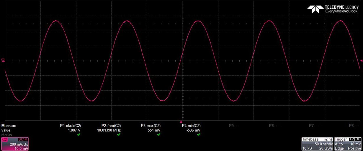
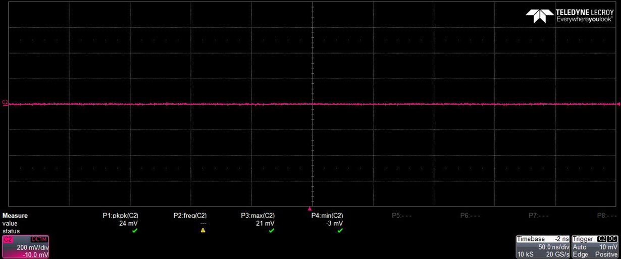
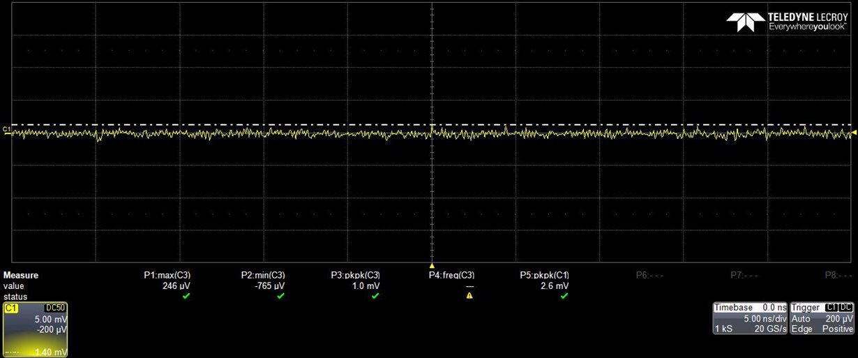
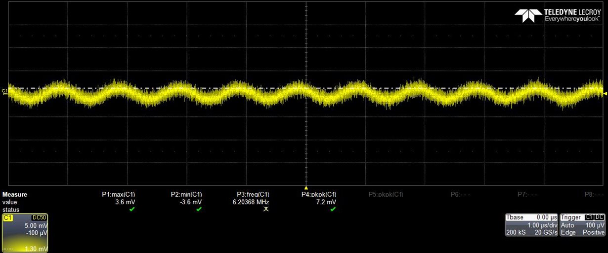
    1. Default EVM

    2. 1pF: no oscillations (set up as current source EVM, but do not have a current source, looking for oscillations) 

    3. 100pF very close to input of amplifier: no oscillations

    4. 100pF far away from amplifier: oscillations

    5.Transistor: oscillations

  • Hello Sima,

    Many thanks for conducting the tests. It is not clear to me how the transistors were connected and whether you used a breadboard or a general purpose PCB. Also, I suggest to use a surface mount device such as BC847 which comes in a SOT23 package.

    However what we need is a circuit which can bring down the input capacitance practically. From what I remember you simulated the transistor based common base circuit and determined that it reduces the ringing.

    I request that you please check that circuit's practical behavior. 

    Thanks,

    Krishna

  • Hello Krishna,

       I used the LMH32401 EVM and connected the transistor to the EVM to match the bootstrap setup. That is true that in the simulation, the transistor compensated the circuit which made it stable and eliminated the ringing. But in practice, the transistors had long leads which probably introduced inductance to the input of the circuit. It is a better option to use surface mount device, but it looks like the SOT23 package the collector and emitter are on different sides of the package which might make it a bit difficult to solder on. I will order it though and try it out. I will be going back into the lab on Tuesday (2/16). 

    Thank you,

    Sima 

  • Hello Krishna,

      The parts I ordered have not arrived yet due to the storms in America's midwest. It is estimated it will arrive sometime early next week. Sorry about the delay on this.

    Thank you,

    Sima

  • Hello Sima,

    Thanks for your update. I understand. Just off the top of my mind , I have a small suggestion. These transistors cost less than a dollar if I'm not wrong.

    If its not too much to ask, is it possible to pick it up from a local electronics parts store like radioshack etc ?

    This is just a suggestion. Please ignore if its not possible. Already your inputs have been valuable.

    Thanks,

    Krishna

  • Hello Sima,

    Its been 2 weeks since my last message. Could you please update us about the transistor circuit ?

    thanks,

    Krishna

  • Hi Krishna,

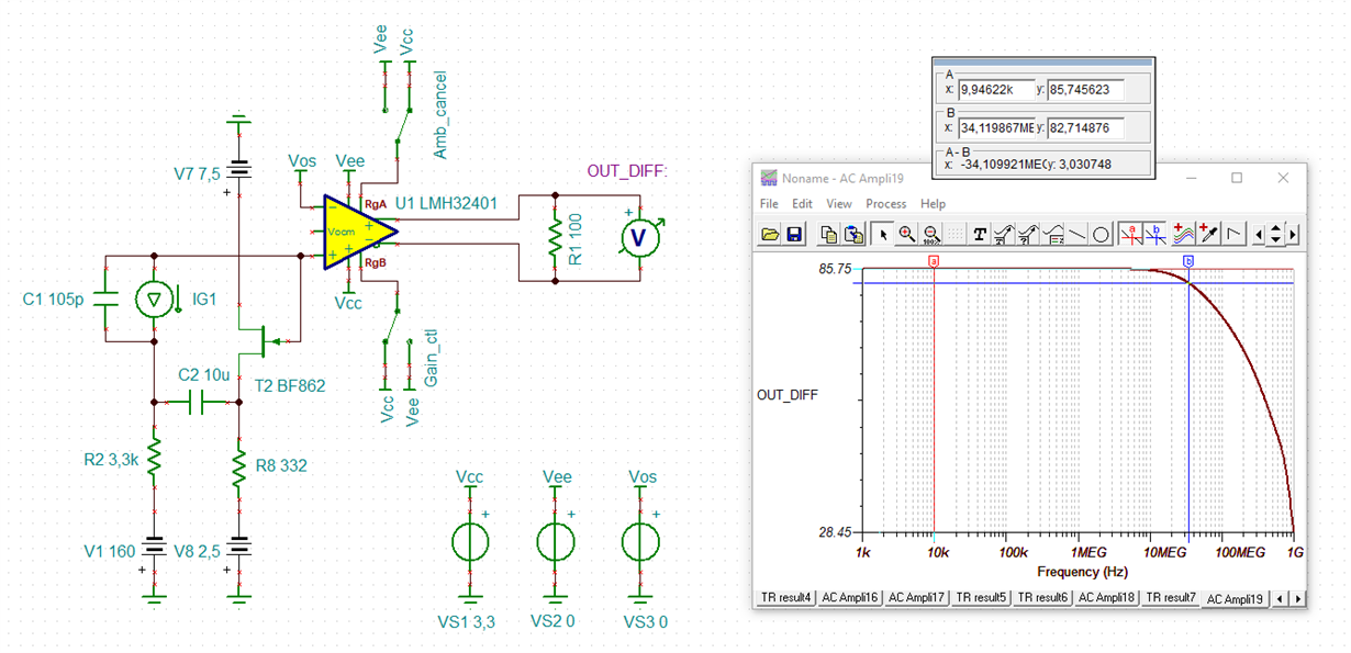
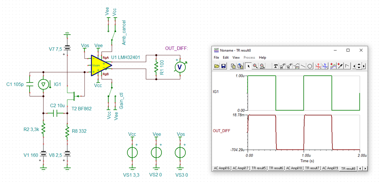
    I would give this circuit a try:

    krishna_lmh32401_1.TSC

    The circuit arround the BF862 is from Michael:

    Kai

  • Hello Kai,

       Thank you for sharing this one amplifier bootstrapping method. This sim has better results than our proposed solution from previous thread. I would suggest this solution over the previous Krishna.

    Hello Krishna,

       I went into the lab Tuesday and Wednesday to test the one transistor solution, and I went through 5 different transistor package types. The smallest one ended up fitting the EVM footprint where the C10 pads are located. The transistor I used is the BC847BM3T5G (package SOT723). I attached the collector and the emitter of the transistor to the C10 footprint, and for the base I had to solder a wire to ground. For the biasing resistor, I placed it on the top R4 pad connected to C10, and the other end I had a wire to bias to negative voltage. Since, I do not have equipment for a current source, I was only looking for oscillations on the scope. I did not see any oscillations for this solution, but power supplies of the amplifier did increase by 2-3mA. I would suggest using Kai/Michael's solution since it does not have the slow rise time as in the previous solution.

    Thank you,

    Sima

  • Hello Kai, thank you for simulating the circuit.

    Hello Sima, as mentioned in my earlier discussions with you, the current source can be easily made by the following:

    The bias voltage at the IN pin of LMH32401 is 2.47 V. If you need to pass current into the IN pin,lets say 10uA for example.

    You could connect a signal generator set to 2.57 V and connect a series resistor of 10 Kohms to it. This puts a 100 mV drop on the 10Kohm resistor and subsequently sink 10 uA current into the IN pin. We are testing all our TIAs like this and it works well.

    If you need to source current out of the IN pin , just lower the output voltage of the signal generator appropriately.

    The input capacitance can be set by connecting a 100 pF cap between the IN pin and the negative bias voltage.

    I hope this is doable.

    Thanks,

    Krishna

  • Hi Sima,

    Kindly provide your test results.

    Thanks,

    Krishna

  • Hello Krishna,

       Thank you for the suggestion, will be able to go into the lab tomorrow and modify the board. 

    Thank you,

    Sima

  • Hello Krishna,

      Unfortunately, I was unable to get the solution to work. I am getting at the output of the amplifier about 70mV with 50uA sunk into the input pin. The signal does not have oscillations, but it is very distorted (looks mostly very very noisy). I believe this is due to the slow rise time of the solution or due to the amount of wires on the board due to all the modifications. There were about 4 in total wires needed. I would strongly suggest going with Kai/Michael's solution instead. This I would not be able to confirm on an EVM. Or I would strongly suggest going with the discrete amplifier as the OPA858 or OPA856. 

    Thank you,

    Sima

  • Hi Sima,

    First things first, you need to pull current OUT of the IN pin, NOT pump current into it. Because this part works well with current drawn out of it.

    To do that, you need to apply negative bias voltage to the series resistor. 

    Please first pulse the current without any capacitor at the input. This will prove whether the part (LMH32401) is working alright.

    Check if you are getting the right transimpedance (10K or 20 K) at the output. I mean, the voltage should be 10K or 20K times the input current.

    And are you 

    Once that is confirmed, then please add capacitance at the input and see its effect.

    Please post some waveforms. Please expedite. This has taken a couple of months already.

    Thanks.

    Krishna

  • Hi Krishna,

    Hello Sima, as mentioned in my earlier discussions with you, the current source can be easily made by the following:

    The bias voltage at the IN pin of LMH32401 is 2.47 V. If you need to pass current into the IN pin,lets say 10uA for example.

    You could connect a signal generator set to 2.57 V and connect a series resistor of 10 Kohms to it. This puts a 100 mV drop on the 10Kohm resistor and subsequently sink 10 uA current into the IN pin. We are testing all our TIAs like this and it works well.

    This turns the LMH32401 into an inverting amplifier. This is no longer a TIA.

    Kai

  • Did you actually try it on the bench ? If it doesn't work try sourcing current out of the IN pin by applying a negative bias voltage. It SHOULD work and this is how we are doing it and it works every single time.

  • Hi Krishna,

    I did not say that the OPAmp is not running well. But as this is no longer a TIA you will not get representative results in understanding the TIA circuit.

    Sima's circuit with the transistor looks very interesting but has the disadvantage that the transistor needs a collector current to flow which the input of LMH32401 has to deliver. This can result in severe DC operating issues.

    That's why I recommended the circuit with the J-FET (a circuit which was recommended by Michael Steffes actually). The J-FET circuit does not draw any drain source current out of the inputs of LMH32401. Only a negligible gate source leakage current is flowing which isn't making any relevant DC issues.

    Would you like to give the J-FET circuit a try?

    This has taken a couple of months already.

    Yes, because you are trying to connect an APD with very high detector capacitance to the LMH32401 which isn't recommended at all. And we did tell you that this is absolutely no good idea. Now, we spend hours and hours with trying to make your circuit still work Relaxed

    I think Sima deserves a big "thank you" for all her work on this.

    Kai

  • Hi Kai,

    We sincerely appreciate the work done by Sima, and are eager to close this issue at the earliest.

    connecting a APD with higher capacitance is not new, and the ones which can be connected with a low capacitance can be operated with a standard op amp TIA circuit. The advantage of LMH32401 is the integrated ambient light DC current cancellation.

    IF this works you could put out an application note for this device.

    Please try with JFET if needed. We are awaiting results of your trials.

    Thanks,

    Krishna

  • Hi Krishna,

    as I'm not an employee of TI and have to bring home the bacon from somewhere else, I cannot build up the JFET circuit for you.

    But if Sima wants to, here are two useful links:

    https://e2e.ti.com/support/amplifiers/f/amplifiers-forum/980967/opa656/3635984?tisearch=e2e-sitesearch&keymatch=2SK2394#3635984

    https://e2e.ti.com/support/amplifiers/f/amplifiers-forum/984620/opa656-opa656/3639302?tisearch=e2e-sitesearch&keymatch=2SK2394#3639302

    Kai

  • Hi Kai,

    Thanks for your comments. Please let Sima continue her work.

    Hi Sima,

    Please let us know about the results of your tests.

    Thanks,

    Krishna

  • Dear All,

    We are happy to announce that we have solved ALL our issues with another IC from Analog devices(AD8015). this is a far better IC with a very good predictable response than your problematic chip.

    We have successfully achieved current to voltage conversion with our APD (Cpd = 105 pF) AND achieved ambient DC light cancellation with a discrete circuit. This is a practical REAL world achievement, not some simulation in a computer.

    I thank my stars that I didn't waste my time on this TI chip(LMH).

    You can close this useless thread filled with comments showing only expertise in computer simulations and equations, but absolutely no idea about real world performances.

    And good luck to this so called tech support from TI !

    Thanks,

    Krishna

  • Hi Krishna,

    glad to hear that you have found an OPAmp finally that seems to forgive your design mistakes Relaxed

    Kai

  • Kai,  They are  design challenges , not mistakes. As you have no idea about the design I am working on , I wonder how you conveniently assumed them as "design mistakes ".Slight smile Looks like you need to know the difference between the two.

    anyway, I like your attiude of hiding your inabilities by calling them "design mistakes". While You can keep working on simulations to prove something can't be solved, I like to see them as challenges and I've succeeded completely.

    and FYI , I didn't use an op amp. Go and check what AD8015 is , before replying. Don't worry ,I have forgiven u for your simulations and pessimistic comments more than that poor IC has forgiven me. For once, at least something works in the real world !

    And Good luck with your simulations and your theory , and your "support". 

    I wonder if Sima is reading this.

  • another thing, I didn't have to use any JFET bootstrapping in my solution. and the IC I used , doesn;t have it either.