Other Parts Discussed in Thread: OPA551
Tool/software:
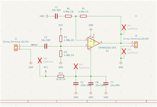
I am building a simple power amplifier using OPA552. I copied a schematic from this document (https://www.ti.com/lit/an/sboa224a/sboa224a.pdf) and thought it is simple enough (I rarely design an analog circuit), but actually it seems not.
Here are screenshot of my schematic and pcb file. The design is to amplifiy a 200kHz sinewave from a signal generator, with a Vpp around 1-5V, to a Vpp of around 10V. The output is used to drive some home-made, capacitive electrode, similar to ultrasonic transducer, but I don't know the exact details.
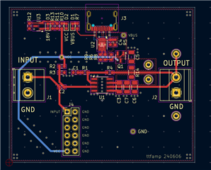
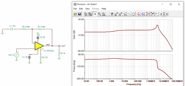
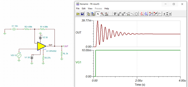
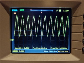
During testing, I applied a voltage of ~12.2V to the opamp. The voltage between R2 and R3 is 6.1~6.2V, biased as expected. But when no input signal is applied, the output with no load, or a 680ohm resistor load, is a wave with a frequency of around 1.6MHz.
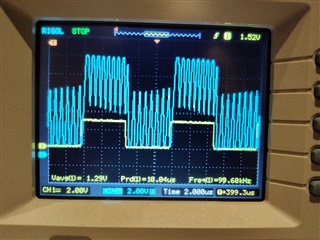
If I generate a 3V square wave from a microcontroller and feed it into the input, I get this result on oscilloscope, where channel 1 (yellow) is the input and channel 2 (blue) is the output. It seems that the input signal is properly amplified but the high frequency noise/oscillation persists and imposed ont the output signal.
Hopefully you guys can figure out how it happens and give me some advice on circuit design (or pcb layout, if my layout put to much parasite capacitance into feedback network).


