This thread has been locked.

If you have a related question, please click the "Ask a related question" button in the top right corner. The newly created question will be automatically linked to this question.

TLC2264: 'Capacitive Load Drive Solution using an Isolation Resistor' App note query

Part Number: TLC2264

Tool/software:

Hello All ,

To address the problem of capacitive oscillations at the TLC2264's output, I have referred to the app note "Capacitive Load Drive Solution using an Isolation Resistor."

In the theory of operation of application note , it is said that the isolation resistor add a zero which in the end gives the phase boost .

How would a series resistor—a non-reactive component—add a zero to the transffer function, is my query here?

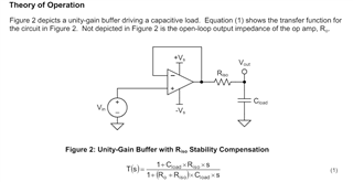
transfer function of output low pass filter adds pole ( 1/(Riso+Ro)*Cload*S+1) to the entire open loop bode plot of op amp  ?

Looking forward to the clarification.

  • Hi Rohan,

    Capacitive oscillations happens when the op-amp's output resistance (R_o) forms an RC circuit with the load capacitor, which makes a pole. When an R_iso is added to this RC circuit, the transfer function changes and adds a zero dependent on R_iso and C_load, and the pole now depends on C_load, R_o, and R_iso.

    For an updated guide on instability and R_iso, please refer to the TI Precision Lab video series on Op-Amps here. We have a group of videos on stability, and the videos specifically relevant to this app note are "Capacitive loads" and "Isolation resistor" under the "Stability" tab. 

    Best,

    Kevin

  • Thanks for the explaination . In the appication note , the output (Vout) is taken after the Riso but in above diagram , its taken before the Riso (Vo) , is frequency response of Vout/Vin and Vo/Vin same ?

  • Hi Rohan,

    The frequency response for Vout/Vin will be different from Vo/Vin because Vout in the application note describes the load voltage and not the voltage node of the op amp output. When evaluating stability, the transfer function is always derived using the output of the op-amp because the transfer function describes the op amp feedback system and its stability. 

    Best,

    Kevin