This thread has been locked.

If you have a related question, please click the "Ask a related question" button in the top right corner. The newly created question will be automatically linked to this question.

INA296A: INA296A3IDDFR

Part Number: INA296A

Tool/software:

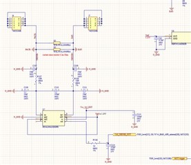
I am using INA296A3IDDFR for current measurement in my BMS application.

Circuit is designed as per attached image. I have provided 1.25 reference voltage as I am doing current measurement for bidirectional application.

1. When current is '0' - voltage at output pin (pin no. 5 0) ~1.25

2. During discharging, negative current, voltage at output pin starts decreasing upto 0 (pin no. 5 0) <1.25 - ) ,during short circuit 0V

3. During charging, positive current, voltage at output pin starts increasing upto 3.3 (pin no. 5 0) >1.25  ) 

IC is functioning as expected, but for 2/ 3 times during running condition, output of the pin became 0 to 0.1V permanently even when current is '0'.

I am not able to find the reason what could have damaged the IC. 

Request your support.

We have performed multiple short circuit tests. During short circuit, it outputs 0V, as soon as BMS turns off MOSFET, current becomes 0 and IC resumes to 1.25V without getting damaged.

 INA296.pdf

INA296.pdf

  • Hello Monica,

    This is due to the fact that the input bias is floating as draws current.  If there is no input current available it floats to a voltage required to power up the input stage.  This could then create a voltage at the inputs and therefore a voltage at the output.  All that is required is ~35µA.  The reason this value can change is parasitic and the start conditions.

    To verify this you could place a resistor to GND on one of the pins.  The Rshunt will provide a short between the two pins.  Something like 50kΩ if you can accept that.  Another option is placing diodes if do not expect the voltage to go below GND by much.

    Regards,

    Javier

  • Dear Javier, Thanks a lot for your response.

    I am not able to understand your point properly. Could you please clarify few points?

    1. I am doing low side current sensing. In+ is connected to Battery Ground (BAT-) and IN- is connected to other side of shunt (Load negative). (Almost equal to battery GNS as Rshunt=100 uohm). How come it is floating?

    2. Connecting Resistance across one of the pin will not lead to incorrect measurement ? I have not seen this on low side current sensing?

    3. Diode should be connected on input side or output side?If on input side

    IC got damaged randomly (output to 0 V) for 2 instances when vehicle was running and some current was flowing. 

  • Hello Monica

    1. I am doing low side current sensing. In+ is connected to Battery Ground (BAT-) and IN- is connected to other side of shunt (Load negative). (Almost equal to battery GNS as Rshunt=100 uohm). How come it is floating?

    I mis-understood and thought your MOSFETS were off and the inputs which included both inputs.

    2. Connecting Resistance across one of the pin will not lead to incorrect measurement ? I have not seen this on low side current sensing?

    3. Diode should be connected on input side or output side?If on input side

    You are correct and my previous suggestion is incorrect.

    Is there any way that during a transient you have the VCM go below -20V?  During transient?  Is the power  3.3V and reference 1.25V independent of the BMS being off?  This part is robust and I have not seen issues while the inputs are in the acceptable range.  So I would not expect damage if within Absolute Max Conditions.

    Regards,

    Javier

  • Maximum voltage at one of the pin should be less than -0.4V.

    3.3V is regulated voltage from BMS.

  • Hello Monica,

    I do not know what the issue could be but from my experience I do not see the INA296 getting damaged in this way. Below is my suggestions on how to try and find what could damage the device.

    I would try and see if you can determine what pin fails to lead you to the root cause. If you can determine this then you can focus on that pin.  Some experiments to perform:  Is the device that gets damaged only has output issues? Can you see if more current is consumed on the supply pin?  Do the input pins draw more current than expected(~35µA)?  Is the output loaded more, is there a voltage drop across R130?  

    Regards,

    Javier

  • I have done multiple tests, and it is observed, every time when IC is getting damaged, Pin no. 1 and 2 are getting short permanently. Out of 10 instances, IC gets damaged once and damaged happens  only during power up. If survive during power up then it works properly. I tried to change input side resistor values R127 and R128.

    When I changed to 0 ohm from 10 ohm. Still getting damaged.

    When increased to 100 ohm gives 0V volt during power up but didn't get damage.

    1. Can I keep 100 ohm, will that cause any other issue? 1 or 2 % Gain error I can adjust in calibration

    2. R130 is used for filtering purpose. Can it cause issue? Shall I remove that? 

    4. As I am using for low side sending, I don't expect input voltage greater than 110V which is maximum limit of Device in case it is causing damage due to transient. I haven't observed any negative transient on scope. I need to check. Shall I try TVS diode for negative transient?

    5. Is there any other option?

  • Monica,

    1. Can I keep 100 ohm, will that cause any other issue? 1 or 2 % Gain error I can adjust in calibration

    Yes you can do this but be aware it will shift gain error and offset error.

    2. R130 is used for filtering purpose. Can it cause issue? Shall I remove that? 

    I do not see an issue with R130 and I would keep it around 1kΩ.

    4. As I am using for low side sending, I don't expect input voltage greater than 110V which is maximum limit of Device in case it is causing damage due to transient. I haven't observed any negative transient on scope. I need to check. Shall I try TVS diode for negative transient?

    I believe the issue could be the negative transient.  I would confirm the input does not go below the -20V.  I would try a TVS diode for the negative transients and see if this will work with the filter resistance much lower.  Transients creating a delta V between N_GND and BAT.  

    5. Is there any other option?

    Looking at the pins during power-up would be helpful in determining the root cause of the issue.  By just increasing the Resistance of the input filter would lean toward a voltage transient.  Can you maybe describe the pin conditions during power up or get a scope shot?  I think the biggest pins to be concerned with is Inputs, Vref and Supply.

    Regards,

    Javier