This thread has been locked.

If you have a related question, please click the "Ask a related question" button in the top right corner. The newly created question will be automatically linked to this question.

XTR117: XTR117 and INA333 , Trim Pot Issue

Part Number: XTR117
Other Parts Discussed in Thread: INA333,

Tool/software:

Hello all, 

So I'm having an issue with a 4-20mA XTR117 chip that is being fed an input from a INA333 instrumentation amplifier. The 333 chip is having it's gain controlled by a bourns potentiometer (model 3224). The issue I'm experiencing is that when I'm trying to adjust the gain at the 333 for a full scale output of 20mA I'm having a hard time getting it to settle. It seems just by touching the adjustment screw on the pot I see the current reading go up by around 20uA or so. If I use a non-conductive tool to adjust the pot I see that the issue goes away and it doesn't jump once the tool is removed from the adjustment screw. So I'm thinking I'm either injecting noise into the inAmp somehow or inadvertently creating a ground loop with the adjustment screw since the ground for the inAmp is referenced to the Iret pin of the XTR117. 

So if anyone has any tips/suggestions I'm all ears on what this problem could be. I have been in touch with Bourns and am waiting to hear what they have to say about this but I thought I would post here also. 

Thanks

  • Hi Joseph,

    You need to provide me input, output, gains and power rails information. 

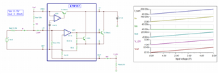
    If the XTR117's input is 0-5V and output is 4-20mA, then the example is shown below, where Vs may be from 10-24Vdc. With 4-20mA output current, you may convert it to voltage via a fixed resistor. 

    XTR117 0-5V 4-20mA 06282024.TSC

    The INA333 takes a differential input voltage and amplify it to higher voltage. I do not know what you have. 

    first, you have to convert 4-20mA into voltage via a fixed precision resistor. 

    second, what is the gains of INA333, since INA333 is a low voltage instrumentation amplifier. 

    It is not good option to use variable pot to replace Rg, because the circuit is sensitive to external noises, parasitic capacitance and noises from you hand when you attempt to adjust the gains. Also, Rg resistance should be 1% or better tolerance type with low temperature coefficient. Anyway, I do not know what you are trying to do. Please provide me with the design requirements. 

    Best,

    Raymond