This thread has been locked.

If you have a related question, please click the "Ask a related question" button in the top right corner. The newly created question will be automatically linked to this question.

TLV3601: problems with applications on small signal detection

Part Number: TLV3601

Tool/software:

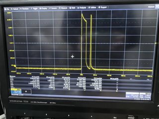
If we input a pulse of 20ns width and 10mV-height and set VREF = 5mV, the output will be like the following picture. It is not correct because of some unexpected narrow pulses. Any solutions to deal with the narrow pulses and make the downward slope steady? Another question is whether VIN-VREF needs to be greater than a certain value or not when we want to detect a smaller signal. If yes, what is the value? Thanks for your answer.
  • Hi Yuan,

    Could you post another oscilloscope picture with two extra channels probing the inputs to the comparator? I'd like to see the signals being fed into the input to get to the root cause of the narrow pulses.

    In addition, are the narrow pulses that you see after your 20ns output pulse consistent? Do they always happen after you pulse the input?

    Another question is whether VIN-VREF needs to be greater than a certain value or not when we want to detect a smaller signal.

    TLV3601 has internal hysteresis. You can see this in the Electrical Characteristics table on page 7 of the TLV3601 datasheet. The typical value for the internal hysteresis is 3mV. This value is centered on the VREF. Assuming your VREF is applied to the inverting input of the comparator, the comparator will output high whenever VIN > VREF + VHYST/2, and output low whenever VIN < VREF - VYHST/2. In your case, the input pulse will need to go above 6.5mV to output high and go below 4.5mV to output low if the comparator you have has the typical internal hysteresis value.

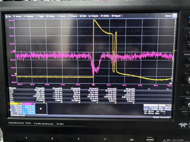
  • Hi Ho, thanks for your answer. The red line in the following picture is differential input (VIN- - VIN+), the large noise causes the narrow pulse. Have any good solutions for that ?

    In this process, I found several questions.

    1) If power supplies the chip but no input signals exists, the output remains high level. Is it valid?

    2) if I press the burst button twice on the pulse generator, the differential input will sometimes be like the red line in the following picture but I don't input the signals of this frequency(VIN+ pulse generator supplies, VIN- DC source supplies). It looks like some oscillation happening. If I reopen the power supply of the chip or lower the VCC voltage or largen signal amplitudes, the oscillation sometimes disappears. Do you have some ideas about that?

  • Hi Yuan,

    Thank you for posting the images. As you said, the input differential seems to be quite noisy. You could make the comparator less sensitive to the noise by implementing external hysteresis with resistors. We have a cookbook that details the calculations to implement a non-inverting comparator with hysteresis circuit: Non-inverting comparator with hysteresis circuit (Rev. A). You could adjust VH such that it is above the noise voltage but below your maximum signal voltage such that the output will not switch high from the noise. 

    1) If power supplies the chip but no input signals exists, the output remains high level. Is it valid?

    Yes, this is valid. If the same voltage is applied to the inputs or if you float the inputs, the output will be determined by the comparator's offset voltage. The comparator output could also chatter, since the comparator is very sensitive to noise in this configuration.

    2) if I press the burst button twice on the pulse generator, the differential input will sometimes be like the red line in the following picture but I don't input the signals of this frequency(VIN+ pulse generator supplies, VIN- DC source supplies). It looks like some oscillation happening. If I reopen the power supply of the chip or lower the VCC voltage or largen signal amplitudes, the oscillation sometimes disappears. Do you have some ideas about that?

    The burst button is probably enabling burst mode, which causes the pulse generator to generate X-cycles of a sine wave. The pink curve you've shown is a perfect 1.25MHz sine wave. Perhaps that is the default frequency for your pulse generator? Try looking for some parameters for "Burst Mode" to confirm. The oscillation is probably disappearing when you lower VCC since you're either turning the comparator off or you are making it so that the inputs are much larger than VCC. The comparator will not switch since it cannot make comparisons too far above the rails.

    Please let me know if you have any additional questions.