- Ask a related questionWhat is a related question?A related question is a question created from another question. When the related question is created, it will be automatically linked to the original question.
Tool/software:
Hello,
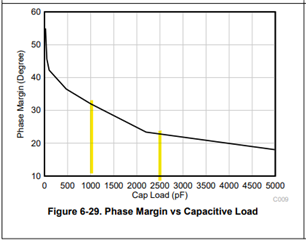
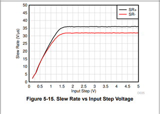
I have a problem with the op amp TL9151SIDBVR. It operates in a differential to single ended circuit. The problem is that for frequencies above 50kHz the sinusoidal signal starts to look like a triangle. This looks like a slew rate problem, but how can this be when its slew rate is 20V/us. What could be the reason for this?
Schematic

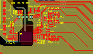
Layout of U8 diff to single ended stage
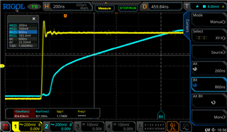
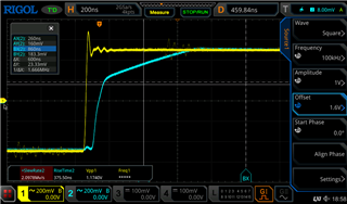
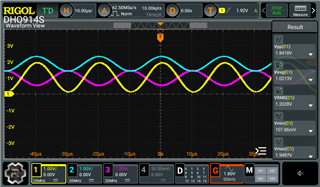
Below Measurements

50 kHz
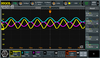
75kHz
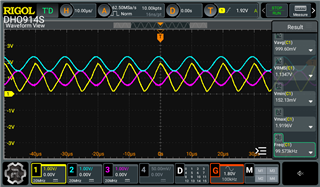
100Khz
Simulation Tina for 100Khz works fine