THS4631: Impedance mismatch problem

Part Number: THS4631

Tool/software:

Hi,

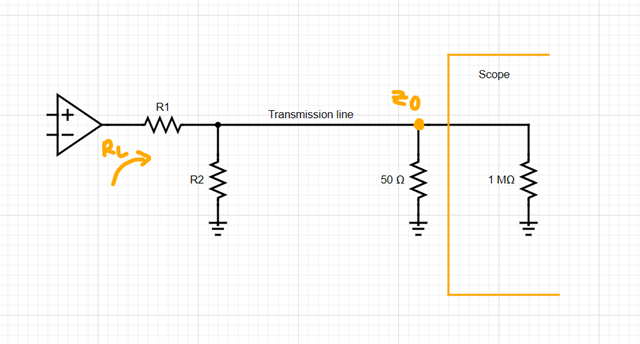
I am using the THS4631 in a high-voltage differential measurement probe where I need to measure an analog signal with a frequency up to 50MHz. A 49.9-ohm resistor is connected between the op-amp's output and the BNC connector. A 50-ohm BNC-BNC cable is used to connect to an oscilloscope with an input impedance of 1MΩ/28pF. I notice that a lot of high-frequency noise is coupled to the oscilloscope input due to impedance mismatch. My output needs to be compatible with a 1MΩ oscilloscope. Is there a way to match the impedance by using any additional components at the op-amp output without using 50-ohm terminators at the oscilloscope input?

Best regards,

Rajhu Baddipadige

  • Hi Rajhu,

    The big thing that may be creating noise is the wire from the output to the scope. Transmission lines have reflections and delay, and you want to minimize this. You can do this by terminating the line on a matched resistor, and by making the line physically shorter.

    Shorten the wire as much as possible, and add a 50Ω resistor from the output to ground. It would be best to place this as close as possible to the input of the oscilloscope, so there is minimal transmission line between the 50Ω load and the scope. If you have to place it before the transmission line, I think that would still help, but it would do a lot less. 

    Lastly, you could try a low pass filter cutting off above 50 MHz, but I don't think that will do much unless it's after the transmission line, in which case the 50Ω resistor would be a better choice.

    Please let me know if you have any questions or if you want me to explain further.

    Best,

    Hypatia

  • Hi Hypatia,

    Thank you very much for your reply.

    Adding a 50-ohm resistor between the output of the operational amplifier and ground will load the OP-AMP. The operational amplifier's output voltage is +/-7V in our application, and it draws +/-140mA from the power supply. Additionally, the differential voltage probe is powered by a 9V battery, which may drain quicker under these conditions.

    Is there any alternative method, such as adding compensation to the operational amplifier, to address this issue?

    Best Regards,

    Raju Baddipadige

  • Raju,

    I see. Then a solution could be to have the 50Ω resistor at the oscilloscope like we were talking about, but also add an attenuator on the board to keep the RL high.

    I looked into an L attenuator, shown labelled below, but other kinds would also work. I wasn't sure of your desired final values, but for an RL = 1kΩ and a Zo = 50Ω, I calculated that you would need a R1 ~= 974Ω and an R2 ~= 52.7Ω

    Of course this also causes attenuation. The attenuation in the example I calculated was 31.8 dB, which may be too much depending on the minimum voltage output you're expecting.

    There is a tradeoff between attenuation and RL, the less attenuation the lower RL is. Hopefully there is a balance that works for you.

    Let me know what you think

    Best,

    Hypatia

    Edit: I noticed the picture was not working, reattached it