Other Parts Discussed in Thread: LM324, OPA172,
Tool/software:
I have an app whereby it's possible that a signal from a Variable Reluctance Sensor gets as high as 70v Pk to Pk on the input to an op-amp configured differential and running at 24V unipolar. This diff amp configuration
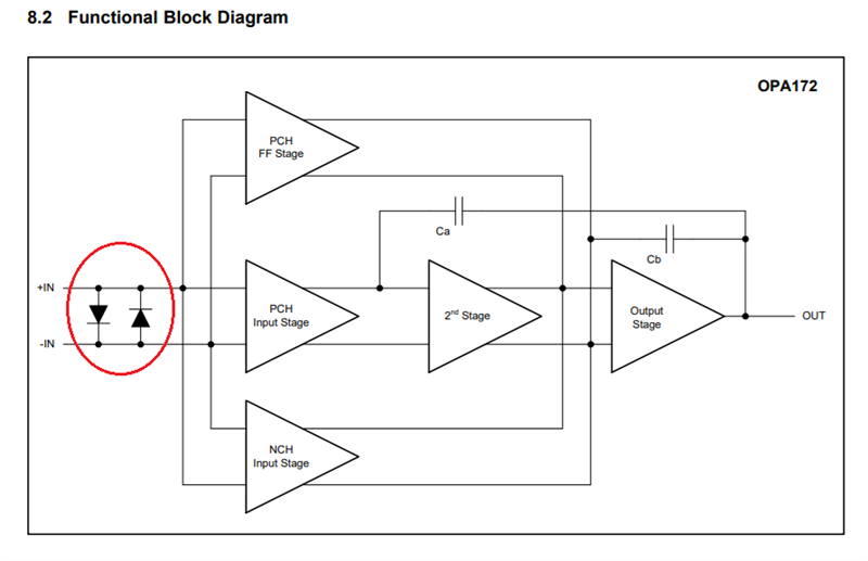
attenuates by 3 to keep within the 24v bounds. I have this design working fine out in the field using the old LM324 device. Simulation exactly matches reality. However, If I change to one of the many new op-amps, transient simulation doesn't complete under the circumstance if the signal runs into either rail. This gives me pause and makes me wonder if the design will work with the newer op-amps.
Is this simulation failure a false negative?
A VR signal can be as low as 0.5v and as high as 100v so I have followed the diff circuit with a compression circuit that works well as the signal is successfully squared up and limited to the bounds of processor power rail, 3.3V.


