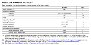
This thread has been locked.

If you have a related question, please click the "Ask a related question" button in the top right corner. The newly created question will be automatically linked to this question.

XTR300: Power sequencing for negative supply.

Part Number: XTR300
Other Parts Discussed in Thread: LM27761,

Tool/software:

Hi, 

I wonder if you would be able to clarify something. I am currently using the XTR300 in a design, along side the LM27761 to generate a -5V for (V-). The XTR300 will be powered asymmetrically, the V+ will be powered from a +15V supply, which will also be used to generate, a regulated 5V5, which subsequently powers the LM27761. 

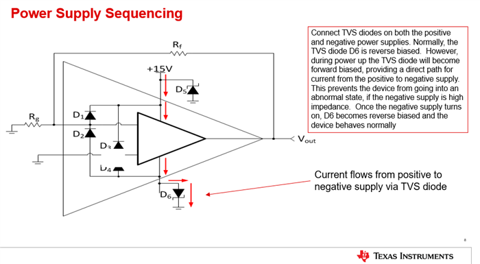
My question is, whether it is acceptable to hold the -V pin at Analogue GND potential (0V), until the -V supply is fully up, if the V+ supply is already up (+15V) ? Noting that the output signal is not enable during this period, and even when enabled the output will only ever be 0-10V.

If that is not acceptable, would holding the device in reset (OD held low) until both supplies are up be an acceptable alternative ? 

Adding a power sequencing IC is unfortunately out of scope at this stage so just trying to understand what we can do that ensures the XTR300 is still operating within its recommended limits. 

Many Thanks,

Edson

  • HI Edson,

    The XTR300 does not have a special power-up sequence requirement.  The main concern is that the Absolute Maximum Rating conditions are not violated at any point in the power up sequence.  For example, the inputs of the device must not exceed the voltage supplies by more than 0.5V. See the Absolute Maximum Ratings table below.

    Yes, it is recommended that you hold the OD control pin low until the power supplies are fully powered up. When the power is turned on or off, the device may generate some glitching of the output because of internal circuit thresholds and internal capacitive charges. Since you are powering the positive supply first and then the negative supply, The OD can be set high after both supplies have turned on and settle. The output disable control (OD) cannot fully suppress glitches during power-on and power-off, but will ensure the device is biased properly prior turning on the output.

    Another general recommendation is to use TVS diodes on both the positive and negative the supplies, this will protect the device against any over-voltage power supply condition or power supply reversal during power on/off.  Lastly, please ensure that the exposed thermal pad is connected to the most negative supply (V-).

    Thank you and Best Regards,

    Luis

  • HI Edson,

    See more detail on supply TVS protection diodes on the figure below.

    Essentially, the TVS diode on the negative supply can provide a path for the current to flow when the negative supply is not turned on or is still high-impedance. 

    Thank you and Best Regards,

    Luis

  • Hi Luis, 

    Great clarification and suggestions, and thanks for the swift response. 

    BR, 

    Edson

  • Hi Edson,

    Thank you,

    Kind Regards,

    Luis

  • Hi Luis- are there any important parameters in speccing the TVS per your recommendation above? Thanks!

  • HI Emily,

    Ideally you would select the TVS diodes with a stand-off voltage set to the nominal supply voltage, and clamping voltage at or below the Absolute Maximum ratings of the XTR300 device. 

    In the circuit above, since the negative supply is -5V, choose a unipolar TVS diode with a stand-off voltage of 5V, and a breakdown voltage and clamping voltage that is relatively close.  As an example, on one typical TVS diode found on the web with a minimum reverse standoff voltage of 5V, will offer a breakdown voltage around 6.2V and a clamping voltage of 9.2V. Similarly, for the positive supply of +15V, choose a unipolar TVS diode with a stand-off voltage of +15V. Some of these diodes will offer a breakdown voltage around ~+16.7V and a clamping voltage around +24V.  The TVS protection diodes will need to be rated to withstand the maximum supply current, or maximum current that can occur in the application during the fault.

    This will work well, since the XTR300 supports a maximum specified supply voltage of ±20V or max asymmetrical supply of (V+) - (V-) =40V during normal operation and can withstand an absolute maximum supply voltage of 44V during a fault condition.

    If you wish to learn more about amplifier protection and selecting diode protection components, please review the TI Precision Lab section on these:

    https://www.ti.com/video/series/precision-labs/ti-precision-labs-op-amps.html

    Under 'Topics' on the right side of the screen, scroll to the bottom to 'Electrical Overstress EOS (4)'.  There are 4 videos on the topic, one of the videos, 'Selecting Components' discusses TVS diodes in good detail.


    Thank you and Best Regards,

    Luis