Tool/software:
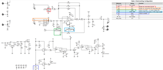
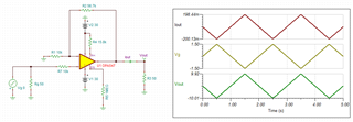
I'm not a EE and I'm a little unsure how to interpret table 4 in the user manual. If possible, I would appreciate a photo, or Figure 2 marked up to clearly indicate the physical jumper positions that correspond to Table 4. I took my best shot at it and did not see a waveform on the scope that matched the input from an AWG (arbitrary waveform generator)..
My use case is this:
- I’m using the amplifier to drive a voice coil flexure linear actuator (inductive load)
- Static travel constant for actuator is.27A/mm about neutral mechanical position
- I chose the OPA547EVM because the manufacturer used the amplifier in a demo and recommended it
- Input to amplifier: AWG, 50 ohm output, triangular waveform, frequency set to 0.5 Hz.
- When connected directly to actuator +/- 10V (20 p-p) drives the device about +/- .6 mm. So less than 200 mA peak
- I started with the amplifier output connected to a scope. AWG connected to J5 input. Scope input set to high impedance.
- Started at low p-p V on the AWG and stopped at around 3 V p-p due to incorrect waveform on scope.
- Power supply to OPA is 2 channel configured bipolar and set to +/- 10V DC, I buzzed it out (read on a forum that this may need to be increased).
- The PS can provide +/- 30V DC at 1.5 A
- I ordered an OVA548EVM to provide more current to drive the actuator to +/- 2 mm, The 547 is on the hairy edge (I think).
I suspect either a jumper is not correct or the supply voltage is too low (or both).
Daniel


