This thread has been locked.

If you have a related question, please click the "Ask a related question" button in the top right corner. The newly created question will be automatically linked to this question.

OPA690: How to apply OPA690 in load control design?

Part Number: OPA690
Other Parts Discussed in Thread: TINA-TI

Tool/software:

HI TI,

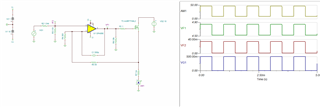
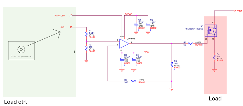
Currently, I need to design a circuit that can accurately control the load current range and load current slope. How should I use OPA690 to achieve this? Specifically, I also want to know how I can use a function generator to achieve my purpose? 

BR,

Delun

  • Hello Delun,

      It looks like you want to drive a high power FET. A few additional questions for your design:

    1. What will your input signal look like, i.e (sin, pulse/square), and if so what is the frequency range or rise time. Or desired switching frequency?
    2. Will you use the PSMN3R7-100BSE? If so, we can base design off these specifications in next replies. I was able to pull up datasheet for VGS and capacitance ranges. Its input capacitance is very large, and we might need to look at dedicated power amplifier/gate drivers depending on the answer to first question.

    Thank you,

    Sima

    1. What will your input signal look like, i.e (sin, pulse/square), and if so what is the frequency range or rise time. Or desired switching frequency?
      >> I don’t really understand the signal pattern and the relationship that affects the output, but if I need it to control the slope of the gate drive, should I use the Sine signal? (My application is hoping to control the Mosfet to control the output load size. And transient load changes and load slope, How should I change my signals specifically to achieve this with the OP?)
    2. Will you use the PSMN3R7-100BSE? If so, we can base design off these specifications in next replies. I was able to pull up datasheet for VGS and capacitance ranges. Its input capacitance is very large, and we might need to look at dedicated power amplifier/gate drivers depending on the answer to first question.>> Eventually I will use Infineon AUIRF7749L2 in parallel for design.
  • HI Sima,

    Could you assist me? I'm still waiting for your feedback. Thanks.

    B/R

    Delun

  • Hello Delun,

      I apologize for the long delay on a solution.

    1. It depends what you are looking for in terms of your output current. It could be any of those inputs, it depends on your required switching time and power. In general, what you need the output to do for your next stage. For example, to drive a laser or some kind of sensor. 
    2. I was able to find the AUIRF7749L2 datasheet and model to simulate:

           In your original schematic, it looks like there is no true negative feedback, we would recommend adding some compensation for stability at overall frequency response. 

      Attached below is the Tina-TI file that you may use to adjust for your design requirements. Overall, you may use OPA690 for your application. 

    OPA690_FET_Driver.TSC

    Thank you,
    Sima