This thread has been locked.

If you have a related question, please click the "Ask a related question" button in the top right corner. The newly created question will be automatically linked to this question.

INA238-Q1: Incorrect current and power values. Related to SHUNT_CAL?

Part Number: INA238-Q1
Other Parts Discussed in Thread: INA238

Tool/software:

I'm developing a driver for the INA238 and am getting incorrect current and power values from the device.  I think it's related to SHUNT_CAL...  I'd appreciate any help with this issue.

On my board, the max expected current is 3A and the Rshunt value is 20 milliOhms.

On initialization and after a reset, these are the register values I am writing to the device.  I was able to confirm that the register writes are successful.

  • SHUNT_CAL
    • Current_LSB = (3 / 2^15) = 91.55 * 1E-6
    • SHUNT_CAL = 819.2*1E6 * 91.55 * 1E-6 * 0.020 * 4 = 5,999.821 ~= 6000
    • Value is 0x1770 aka 6000
  • CONFIG
    • Value is 0x10.  set bit #4 aka ADCRANGE=1
    • Means shunt full range scale is +/- 40.96mV
  • ADC_CONFIG
    • MODE==0xF
    • VBUSCT==0b101
    • VSHCT==0b101
    • VTCT==0b101
    • AVG==0b001
    • Value is 0xFB69

I'm using these equations to calculate current and power with the raw register values:

(final current) = CURRENT_LSB * (raw CURRENT reg value)

(final power) = 0.2 * CURRENT_LSB * (bits [15:0] of raw POWER reg value)

These are the results I'm getting:

Manufacturer ID 21577.
Voltage 54387 MilliVolts.
Power 207 MilliWatts.
Current 3 MilliAmps.

Current should be around 300 mA...

Is there anything else I can do to verify the code and hardware?

  • Hi Vincent,

    First off, your max current * Rshunt = Vshunt=60mV which is beyond the ADC range of +/- 40.96mV.

     To fully debug this issue, I'd need the complete set of raw register values you see. If fixing the ADC range does not solve your issue, please follow up with the raw register data.

    Best,
    Mallika Senthil

  • Hi Mallika,

    Thanks for the tip.  To fix the ADC range, I changed Rshunt to 12mOhms.  Max expected current is still 3A.

    Now, my expected values are 26.3V, 5.2W, and 0.2A. 

    This makes SHUNT_CAL = 819.2 * 1E6 * CURRENT_LSB * Rshunt * 4 = (819.2 * 1E6) * (91.55 * 1E-6) * 0.012 * 4 = 3600

    The results I get are 26.3V, 13.6W, and 0.5A.

    The raw POWER reg value of this result is 0xB5604 aka 742916, and the raw CURRENT reg value is 0x1555 aka 5461.

    If I expect 5.2W, then 5.2 = 0.2 * CURRENT_LSB * POWER = 0.2 * (91.55 * 1E-6) * POWER.

    The raw POWER reg value should be 283,997 aka 0x4555D.

    13.6W corresponds to a raw POWER reg value of 742763 aka B556B.

    For CURRENT, the expected 0.2A should come from a raw register value of (0.2 / (91.55 * 1E-6) = 5461 aka 0x888.

    The result .5A comes from a raw reg value of (0.5 / (91.55 * 1E-6) = 5461 aka 0x1555.

  • Hi Vincent,

    Your calculations are all correct so I don't think the issue is on the software side. What is the Vshunt value you measure on your hardware set up and how are you measuring your expected values?

    Best,
    Mallika Senthil

  • The expected values come from a power supply and electronic load.  Vshunt is 0.002V.

    For CURRENT_LSB, how should max expected current be determined?  Is it calculated via Vshunt and Rshunt?

  • The I_max can be determined by the max Vshunt (which is the max value measurable in the ADC range - 40.96mV in this case) and Rshunt (12mOhms). I_max = 3.41 A, this is the maximum current you can measure on this device with a 12m shunt resistor. 

    In that case,

    SHUNT_CAL = (819.2e6)*(3.41/2e15)*(12e-3)*4= 4092

    Best,
    Mallika Senthil

  • Thanks Mallika for the clarification.  I reconfigured SHUNT_CAL to use Imax=3.41A, but unfortunately I get the same results.

  • Interesting, could you send me schematic of your hardware setup showing where you probe voltage, power and current.

    Best,
    Mallika Senthil

  • We are using an electronic load to simulate power going across the shunt resistor.  On the INA238 development kit (https://www.ti.com/tool/INA228_237_238EVM#tech-docs),  we are connecting the electronic load to IN- test hook and pulling a small load of 0.2A. The electronic load reads us the voltage, current, and power at that test point.

    Currently, we're injecting 15VDC into the IN+ test hook and also injecting 3.3VDC into VS test hook.  Please let me know if you need additional information.

    The expected values now are 15V, 0.2A, and 3.0W.

    --------------

    It appears like with various loads (expected voltage, power, and current), the (expected values) == 0.4* (actual values).

  • Hi Vincent,

    What is the Vshunt raw register value you get and is the probed Vshunt value still 2mV? Also, please check that your shunt resistor is of the value you intended it to be.

    Best,

    Mallika Senthil

  • The raw Vshunt register value is 4961.  With ADCRANGE=1, 4961 * 1.25uV = 6.2mV.  Our multimeter measures 2mV.

    With 6.2mV and Rshunt=0.012 ohms (the measured value is pretty close), Ishunt is 0.516A which matches the value calculated from the CURRENT register...

  • Hi Vincent,

    From the information you've given me so far, I can conclude that the INA238 is configured correctly since your Vshunt and I_load values correlate with the register map values. My next debugging suggestion would be to:

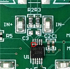
    1. Test Vsense on the device pins directly as shown in the diagram below. Incorrect soldering may be throwing off the values.
    2. Ensure your multimeter is configured to measure beyond 2mV, I hope its not railing out.
    3. Try using a different multimeter
    4. Try the test on a different INA238 EVM


    Best,
    Mallika Senthil

  • Thanks Mallika.  I'm able to measure 6mV for Vsense (via the blank pads just above).

    So if the measured Vsense=6.2mV, and Vshunt and I_load from the registers are 6.2mV and 0.516A respectively, then is the INA238 itself correct?  This is not what the electronic load is pulling (0.2A and 3.0W)...

  • Yes, the INA238 is working as it should.
    Sometimes the e-load isn't as accurate as we expect it to be, that's why using a multimeter to probe voltage or current as close as possible to the device is recommended. I hope this has resolved your queries.

    Best,
    Mallika Senthil

  • Thanks Mallika.  Knowing that, we double checked one of our power supplies and determined it was faulty.  With a different power supply, the INA238 and firmware returned our expected values.

    I appreciate your help!