This thread has been locked.

If you have a related question, please click the "Ask a related question" button in the top right corner. The newly created question will be automatically linked to this question.

OPA453: What is the max output current?

Part Number: OPA453
Other Parts Discussed in Thread: OPA548, OPA547, OPA452, OPA593EVM, OPA593, OPA552, OPA551

Tool/software:

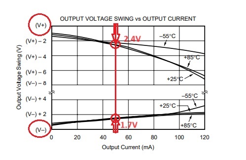
I saw the datasheet shown minimum output current is ±50mA. I don't see any maximum value remarking on electrical characteristics table.

However, the OPA453TA shown short-circuit current Isc typical value is ±125mA.

Which means if I have a +75mA and -23mA output current driving application. It is still safe for OPA453TA?

Regards,

Otis

  • That output current specification is, by itself, not a useful value.

    The output voltage range depends on the output current (see the top right figure on p. 6). The datasheet guarantees that you can get at least 50 mA when the output range is between (V−) + 5 V and (V+) −5.5 V. When you want a wider output voltage range, you must use smaller currents; when you need larger currents, you must restrict the voltage range further.

    Safe values are specified in the absolute maximum ratings; also see figure 3 for the safe operating area.

  • The typical short-circuit current of OPA453 is +/-125mA but over process, supply voltage and junction temperature you can count only on output current of +/-50mA. 

    Of course, as Clemens explained above, all these apply only if you are NOT driving the output too close to either rail.  Thus, for example, in order to source 50mA current you cannot drive the output closer than 2.4V below positive rail (V+) and to sink 50mA current you have to drive the output more than 1.7V above negative rail (V-) - see below.

  • Thanks for replying.
    According to the diagram of output swing shown, if my OPA output current higher than +/-50mA such like +/-75mA. Which means to look for high output current OPA like OPA547 or OPA548 that can solve my problem. No need to worry about output volage swing vs output current.
    BTW, both of the OPA547 and OPA548 are pin to pin for OPA453, right? My OPA supply voltage is V+=40V, V-=0V. Can I replace it by OPA547 or OPA548 directly?

  • Hi Otis, 

    Marek is traveling. Maybe I am able to assist you. 

    According to the diagram of output swing shown, if my OPA output current higher than +/-50mA such like +/-75mA.

    Below is the OPA452/OPA453 SOA plot. If the output current requirements is closed to +/-75mA, you are unable to adapt OPA452/OPA453. 


    May I propose OPA593, which is 85V, ±250mA power amplifier? The WSON package size is only 4mmx4mm, and the amplifier's heat dissipation can be dissipated via the PCB board. OPA593EVM is linked below. 

    https://www.ti.com/lit/ug/sbou268/sbou268.pdf?ts=1723151608418&ref_url=https%253A%252F%252Fwww.ti.com%252Ftool%252FOPA593EVM

    If you are able to provide me the detail requirements, I will be happy to simulate the scenario for you. 

    Best,

    Raymond

  • Hi Raymond,
    Because I would like to OPA453TA (TO-220-7) pin to pin package design due to PCB design already been fixed, so that is why I selected OPA547 and OPA548 not OPA593 WSON-12 package to directly solve the exceeding SOA issue. Does it make sense to use OPA547 or OPA548?

    Many thanks,

    Otis

  • BTW, the OPA will be very similar to below link p.9 current mirror design. The +Vs=40V, +Vs=GND. The slightly difference is without C1 and R4 being replaced by Zener diode in the back of R3 cross PMOS g-s to ensure PMOS "ON"
    Implementation_and_Applications_of_Current_Sources_and_Current_Receivers\

  • Hi Otis,

    Does it make sense to use OPA547 or OPA548?

    Yes, you can use OPA547 or OPA548. In addition OPA551 may work as well. OPA552 is decompensate op amp, and it needs gain ≥ 5V/V in order to be stable. 

    https://www.ti.com/amplifier-circuit/op-amps/power/products.html?keyMatch=power%20amplifier&tisearch=search-everything#sort=1261max;desc&

    BTW, the OPA will be very similar to below link p.9 current mirror design.

    Regarding to the current mirror circuit design, enclosed in the application note. You are required to check for the loop stability; R3 and R5 values need to be higher in order to have the adequate phase margin in the circuit below (I recalled that the values are approx. 1kΩ range). 

    https://www.ti.com/lit/ug/slau502/slau502.pdf?ts=1723206871083

    If you have other questions, please let us know. 

    Best,

    Raymond

  • Hi Raymond,

    Can OPA548T-1 supply voltage be used to V+=40V and V-=0V? When that situation what the max operating temperature is?

    If i would like pin to pin with OPA453TA-1, could I let pin3 and pin 7 open connection? Because I don't use it function in original OPA453TA-1.

    BR,
    Otis

  • Hi Otis,

    Can OPA548T-1 supply voltage be used to V+=40V and V-=0V? When that situation what the max operating temperature is?

    Yes, OPA548T-1 is able to operated with single supply rail, say 40Vdc and GND. It is within the recommended operating supply voltage.

    The OPA548T-1 datasheet's guaranteed performance is specified between -40C and +85C (Tamb). However, it can be operated up to 125C. 

    The max. operating temperature is shown is the SOA curve, when |Vs| - |Vo| delta voltage is the largest at the highest source/sink current.  

    If i would like pin to pin with OPA453TA-1, could I let pin3 and pin 7 open connection?

    You may leave pin7 or E/S open, but ILIM pin has to connect to V-. In this case, pin3 is required to tie to GND in single supply rail operation, where Ilimit = 5A. 

    If you have other questions, please let me know. 

    Best,

    Raymond