This thread has been locked.

If you have a related question, please click the "Ask a related question" button in the top right corner. The newly created question will be automatically linked to this question.

OPA855: Transimpedance amplifier's output waveform is associated with input current?

Part Number: OPA855

Tool/software:

I use OPA855 with transimpedance amplfier with APD(Avalanceh PhotoDiode).

I want to set proper feedback resistor for wide input signal's dynamic range.

First, I set a feedback resistor to a few hundresd ohm (100 ~ 200 ohms).

When the input signal was saturated, it was first confirmed that the pulse width increased as expected.

However, after that, it was confirmed that the pulse was unexpectedly distorted.

(feedback resistor * current is larger than 5[V]) signal's rise edge is distorted. (green circle of below figure)

If input current be larger, distortion also be larger. The pulse does not maintain its trapezoidal shape.
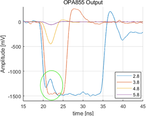
 Legend: Magnitude of optical filter, '+1.0' means power of laser is attenuated by a factor of 10.

And then, I set a feedback resistor 5kohm.

However, in this time, although (feedback resistor * current) is almost 50[V] but a pulse doesn't distort. (It means pulse width increases, but it remains trapezoidal.)

So, I have a question about the realationship of input current and TIA's output.

Is a OPA855's output waveform affected to the input current?

I can't find a information about this in OPA855's datasheet.

  • Hello JeongRok,

      Does your pulse rise time decrease during the increase of optical power or input current of the APD? I have seen previous customer applications where this was the case, and the TIA was driving a faster signal with the addition to the increase in power.

      What is the expected rise time range (frequency) and what is your APDs input capacitance? 

    Thank you,

    Sima 

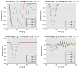
  • The figure below is a output of the TIA(OPA855) while adjusting the optical filter from 3.0 to 7.5.

    (Ensemble average of a 20 times measurements)

    (TIA(OPA855)'s feedback resistor is 5kohm, feedback capacitor is 0.3pF)

    The rise time from 4.3 to 6.0 is shown in the following table, which is a range where the signal is not saturated and the effect of noise is sufficiently ignored.

    4.3 4.5 4.8 5.0 5.3 5.5 5.8 6.0
    1.68[ns] 1.73[ns] 1.75[ns] 1.93[ns] 2.02[ns] 2.11[ns] 2.03[ns] 1.89[ns]

    According to the table above, pulse rise time looks like decreasing during the increase of input current of the APD.

    This LD system has a typical 1.4ns rise time.

    I'm using MTAPD-06-013. Capacitance of this APD is 1.2pF. and 0.6ns rise time.

  • Hello JeongRok,

      Thank you for providing this data, it was very helpful. Since the rise time does decrease with increasing current, the output is distorting due to it being correlated to the affect on input rise-time rather than the input current. 

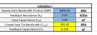
      I was looking at the calculations, and OPA855 should be able to handle up to 2GHz, or 0.5ns of rise time with an estimated input capacitance of 3pF (APD + internal caps of OPA855 + PCB estimated capacitance) and 100Ohm feedback resistor. More than this, you might run into instability which is why you see the overshoot/undershoot response. 

     With 5kOhm feedback resistor, you can achieve up to 300MHz with 65 degrees of phase margin (0.707 or Butterworth response). 


     Would you be able to try at your original 100Ohm feedback resistance, but increase the feedback capacitance slightly to 1pF or 2pF?


    Thank you,

    Sima 

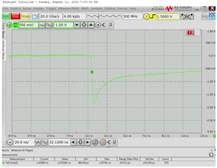
  • I try as your advice using 100ohm feedback resistor, and 1pF feedback capacitor.

    This signal's fall time is 1.3[ns] (679 counts's average by oscilloscope), but signal's tail is too long.

    I think long tail is casued by large feedback capacitance.

    Is it possible to organize the answer to my first question('why my waveform distorted when large input comes') as below?

    1. large signal has short rise time when signal saturated
    2. Short rise time is equal with high frequency signal
    3. My TIA circuit is oscillated when high frequency signal comes.

    Then I have some additional questions,

    • Is it a kind of 'oscillation' where the pulses fail to keep trapezoidal when a big signal comes in?
    • If so, why doesn't the back of the signal show the same shape as the oscillation?