This thread has been locked.

If you have a related question, please click the "Ask a related question" button in the top right corner. The newly created question will be automatically linked to this question.

INA500: Alternate use of INA500 for interfacing low speed digital input (~120Hz)

Part Number: INA500

Tool/software:

Hello E2E Community,

We are evaluating the use INA500 to interface with two types of sensor inputs:

  1. Single ended 0-3.3V analog voltage input from temperature sensor
  2. Single ended 0-5V digital square wave ~120Hz input from hall effect sensor

The square wave shall be fed to the timer input on MCU with digital filters for accommodating the waveform distortion if & as encountered in this configuration.

Kindly guide will we be able to use the same pin inputs for 120Hz digital square wave input as well, we are trying to check if we can combine the functionality of both these sensor inputs into same pin-out on our board.

Kindly guide.

  • Hello Neet,

    For single ended input it is not necessary to chose an instrument amplifier.

    Should the final output be a DC voltage or should the 120Hz signal to be passed as is?

    What is the desired full scale output range? Is it OK if smaller input choice only uses a portion of full output range?

    What supply voltages are available to do this?

  • Hello Ron,

    We have long cables coming from field side which may carry common mode noise - hence we are evaluating the use of INA500 as this is within our budget instead of using Common Mode Choke.

    The input signal is 95% of the time Analog voltage 0-3.3V from temperature sensor from 7-8m long twisted pair cable.

    The input signal can be a 120Hz 0-5V Square wave from Hall effect sensor.

    Kindly guide if we are making correct assumptions. Our objective is to maximize the pin utilization.

  • Should the final output be a DC voltage or should the 120Hz signal to be passed as is?

    The 120Hz should be passed as is in square-ish waveform, we will use digital filters to ignore the distortion (overshoots/undershoots/ringing) caused by the INA500

  • What is the desired full scale output range? Is it OK if smaller input choice only uses a portion of full output range?

    1:1 is the desired output range with respect to the input signal 0-3.3V/5V.

    Input Vcc 5V.

  • Neet,

    1:1 Vout = Vin, where VIN is ([IN+] - [IN-]). REF = 0V, V+ 5V, V- 0V

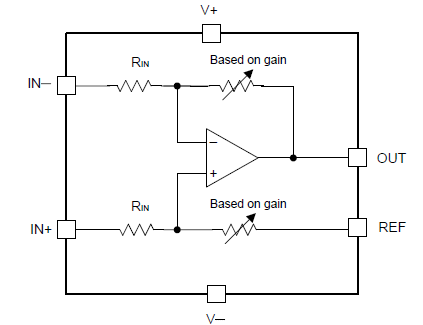
    For the common mode noise, there is limited negative rejection. REF is 0V so internal amplifier is noninverting pin voltage is [IN+] / 2 in volts. The internal amplifier needs input voltage within the power rails. Therefore [IN+] pin should not go below V- supply voltage. 

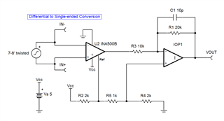
    For more noise rejection range, consider gain of 0.5 and VREF and 2.5V. A second amplifier can convert [2.5V to 5V] into [0 to 5V] 

  • 1:1 Vout = Vin, where VIN is ([IN+] - [IN-]). REF = 0V, V+ 5V, V- 0V

    Correct, above is the configuration.

    1. We will be using Unidirectional ESD diodes for clamping any negative transients
    2. We can also use RC based LPF on inputs if need be (kindly suggest)
    3. Can INA500 transfer a ~120Hz Square wave without significant distortion?
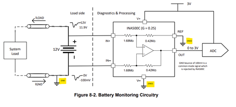
  • As per the Application Hints in the datasheet - we can simply connect the IN+ & IN- to an analog input with separate ground which can be isolated from the V+ & V-, right?

  • Neet,

    The slew rate is typically 0.2V/us so 25us typical edge rates.

    For fully isolated grounds, internal inputs become 1/2 of VOUT; however the measurement connection loosely connects the two ground systems. If anything else creates a change in the two ground difference voltage, then that could (probably would) exceed the input common mode range of INA500.

    We do have fully isolated amplifiers that are galvanically isolated, so they accept huge ground differences.  

  • Hello ,

    1. We do not need a galvanic isolation, also the cost of isolated amplifier is high for the project budget
    2. We would however benefit from some finite common mode noise immunity (ballpark estimating this is where we seek your assistance)
    3. We plan to power analog voltage (0-3.3V) temperature sensor using a coin cell battery & the sensor shall be about 7-8m away from the INA500 so we do not expect ground potential difference more than 0.5V at worst.
    4. We plan to also use a 120Hz square wave as input via the same INA500 in 5% of the cases when we would require it - same battery configuration.

    Kindly guide with crisp response if we should explore using this INA500 given our use case, kindly ask me more details if necessary - we are not very well versed with analog circuit design, hence reaching out to the E2E community.

  • Neet,

    For isolated balanced difference input with common mode noise rejection, I suggest adding a reference which required lower gain of INA500B and a post amplifier to get gain back.

    For the 5V 120Hz input the 5V VIH might be bigger then the application's 5V supply. That will clip at application's 5V supply. It may be best shrink output to always be with in the applications power rails (this is faster, no overload recovery time). To do this set R1 to 18K. that makes VOUT = VIN * 90% + 0.2V (with VCC=5V)

    diff to single (VCM noise).TSC