This thread has been locked.

If you have a related question, please click the "Ask a related question" button in the top right corner. The newly created question will be automatically linked to this question.

INA240-Q1: Bias current

Part Number: INA240-Q1
Other Parts Discussed in Thread: INA240, TMUX1511, TMUX1112, TMUX7221

Tool/software:

Hi, I am using INA240A2 in one of the battery operated application.

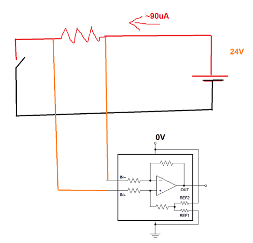
So, I am using 2 IC's which are contributing around 180uA (90uA+90uA) quiescent current when the INA240 is not powered. But 24V is always available.

May I know the current flow path, so that I can try to block it when the Part INA240A2 is not powered.
  • According to the functional block diagram, the current flows out of the OUT/REF pins, so you should be able to disconnect them with switches like the TMUX1511 or TMUX1112.

    To disconnect the IN pins instead, you would need high-voltage switches like the TMUX7221.

  • Hi,

    Part of the Ib flows out of ground pin. Not considering practicality, the cleanest approach would be cutting off the inputs.

    Regards,

    Guang

  • Hi, I have disconnected ground from the rest of the circuit, still there was no change. Even I increased the input resistance, that is not helping.

    My objective is to reduce the current to half, (from 90uA to 45uA appx).

    If I connect any switch on the input lines, it will affect sensor accuracy as well as it cannot be a cost effective solution!.

    Hint: May I know the internal block difference between INA240A2 and INA241A3 as the later one has less bias current!

  • Hi,

    For all practical purposes, there is little difference in terms of internal block between INA240A2 and INA241A3. The only difference is gain setting resistors which should have little, if any impact on input bias current.

    Regards,

    Guang