This thread has been locked.

If you have a related question, please click the "Ask a related question" button in the top right corner. The newly created question will be automatically linked to this question.

OPA855: Troubleshooting High-Frequency Oscillations in OPA855-based TIA Circuit for PMT Signal Amplification

Part Number: OPA855
Other Parts Discussed in Thread: THS4302

Tool/software:

Hi,

I'm seeking some assistance with an issue I'm encountering in my TIA (Transimpedance Amplifier) circuit based on the OPA855 op-amp. The circuit was previously working well(designed a few years back and utilized a resistive (as well as capacitive) network in the inverting input with a total BW of 200MHz), providing sufficient bandwidth for my needs, but now I'm trying to optimize the design by removing the resistive network at the inverting input. 

To provide some more context, the TIA is used to convert PMT (Photomultiplier Tube) current to voltage, with a second stage THS4302 amplifier applied afterwards. Unfortunately, I'm experiencing oscillations at around 3.3GHz which move a little from around 2GHz- 3GHz over my different experiments.

The key details are as follows:

  • The required gain for the first stage is 249, with a target bandwidth of 450MHz.
  • My signal (in operational mode) contains different harmonic and isn’t a pure sine.
  • The PMT has an input capacitance of approximately 10pF, while I consider the OPA855 to have capacitance of around 0.8pF.
  • The distance between the last PMT dynode and the inverting input is about 5mm, with 3 x 0402 resistor slots, which I estimate adds around 2nH of inductance.
  • I've implemented good layout practices (there are no power planes underneath the feedback network) and have ensured proper power supply filtering.
  • I've tried removing the 10Ohm RISO resistor, but I'm still encountering oscillations.
  • Adding a feedback capacitor in the range of 0.2pF (parasitic) all the way up to 1.5pF didn't seem to have a significant impact in reducing oscillations.
  • Measurement setup:

-Power supply: OPAs are powered with ±2.2V.

-Input condition: No light input to the PMT, resulting in no input signal to the OPA855.

-Output connection: Second stage output is connected to a spectrum analyzer.

-Connection details: Impedance: 50 ohm

-Cable: MMCX to SMA

  • I used the TIA calculator suggested here a few times as well as used manual calculations for Cf with no luck at getting rid of the oscillations.
  • Im simulating with Orcad P-Spice: showing here the first stage - I’m pretty sure that’s where the problem is rooted (the second stage is not more than a THS4302 - signal connected to the noninverting input and the inverting input is connected to GND).


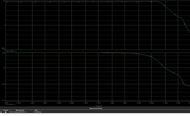
I can already see that phase margin is a problem in this case but the question is what causes it and how can it be improved( and get rid of the oscillations..).

Thanks

  • Hi,

    I was able to simulate the TIA configuration you highlighted, and it is resulting in relatively good phase margin. The distance between the PD and the input is always a concern as this distance does have a negative impact in the stability of the device like you mentioned. Simulation does show this as I increase the parasitic inductance as well. The addition of the 10-ohm series resistor also has an ill effect on the stability so it would be ideal to short this component. One test worth trying to see if we can get the device to a stable point would be to increase the Rf resistor to say 500-ohms and place a feedback capacitor of around 0.9pF. We can try to reduce the bandwidth of the TIA by adjusting these values to see if this helps stabilize the circuit. You did mention you previously got this circuit to work. Was this with the same board and PD? Meaning the only change has been the Rf and capacitor you have tried to adjust.

    Best Regards,

    Ignacio

  • Hi, thanks for your reply.

    I also simulated with TINA TI and got a decent PM and high BW while simulating with Pspice yields in insufficient results - low PM and low BW. I did try to remove the 10ohm resistor at the input of the inverting input and replaced with 0 ohm instead - with no luck at removing the oscillations. I did get this circuit stable as I said by utilizing the 3 resistors and capacitor that can be found in the simulation schematic. They are connected to the input of the inverting input. R1,R2 was in the ~30 ohm range and R3 was slightly smaller, and C135 was 3pF and the circuit worked fine but with a much lower BW compared to simulation or to calculations - somewhere around 170MHz. It was with the same board and same PMT and same layout. The distance between the PMT's last dynode (and not photodiode) is about 5mm (which includes the path through this resistive network as I mentioned earlier).  I didn't really try to tweak Rf since I need the gain to be 249 - though I did try to put two 125 resistors in series (instead of one 249) to change parasitic behavior a little but with no luck.

    All in all - playing with Cf has never proved helpful in stabilizing this circuit.

    What am I missing here?

  • Hi,

    I agree with you that it does not seem to be a component selection issue as the components you chose for Rf and Cf are within the range we would need for a stable TIA circuit. Could you share the layout of the circuit. It will help to see if there are any blatant concerns with the layout itself. 

    Best Regards,

    Ignacio