This thread has been locked.

If you have a related question, please click the "Ask a related question" button in the top right corner. The newly created question will be automatically linked to this question.

PGA855EVM: Changing Gain Changes Bias Current

Part Number: PGA855EVM
Other Parts Discussed in Thread: PGA855,

Tool/software:

Hi TI,

I found that when I change the gain setting on the EVM, the bias current also changes.

The PGA855 is powered from +30V and -4V, with VCC = LVDD+, VEE = LVSS-.

Inputs are connected to GND, and outputs are left open. I can measure 12.94V (close to 13V from mid supply internal VCM biasing).

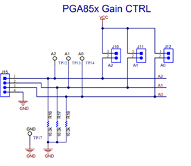
The gain setting is changed by shorting/ opening the jumper on A0, A1 and A2 jumpers.

What I observed is that, with more switch connected, it seems my bias current also increases.

At 000 gain, the positive and negative bias currents are equal.

At 100, the positive bias current increased by 3mA.

Then at 110 or 011, the current increased by another 3mA. 

At full 111 gain, the current is now at 3x 3mA increase from 000 gain.

I checked the digital pins settings, but I think I am not overstressing their voltage limit:

There is also pull down resistors at the gain setting jumpers, but with 100kohms, I am not expecting >1mA of increase.

What is this behavior that I am looking at? Should I be concerned?

  • Hi Hao,

    When you mention the "bias current", I assume you are discussing to the power supply current consumption on the post above, and not the PGA input bias current.  The PGA855 input bias current through the PGA input pins is around 500pA typical and 1.8nA max at room temperature regardless of gain.

    The PGA855 device stand-alone total supply current consumption at room temperature, through both the input and output stage supplies should be around 6.5mA max total when setting the device with bipolar ±15V supplies.  This is assuming the PGA output is unloaded, and the differential input voltage input is around 0V. 

    As you have mention, the PGA855EVM has a few external components including pull-down resistors on the A0, A1, A2 gain setting pins, and a 10k+10k voltage divider on the VOCM pin that consume additional current.   The PGA855EVM allows you to set the gain with jumpers for flexibility.  The gain control pins have an external 10.0kΩ R16, R17, R18 pull-down resistors to GND, and when you pull the gain pins high to the +30V supply on the EVM, the current consumption changes by 30V/10kΩ=3mA for each pin. The complete PGA855EVM schematic on Figure 8-1 and the Bill of Materials (BOM) shows the correct values for R16, R17, R18 at 10.0kΩ.  The simplified block diagrams of figure 2-1, figure 6-1 show 100k but this is a typographical error that will need to be corrected.

    Please keep in mind, when using the PGA855 in most real world applications, the PGA855 gain control pins A0, A1, A2 are driven high by a microcontroller, without the need of the pull-down resistors, so there is no significant change in overall current consumption when changing the PGA gain.

    Thank you and Regards,

    Luis   

  • Aha, so those are 10kohms!

    Thanks Luis for the information, totally should have looked at the actual BOM and schematic.

  • Thank you Hao, 

    Let us know if you need anything.

    Kind Regards,

    Luis