
- Ask a related questionWhat is a related question?A related question is a question created from another question. When the related question is created, it will be automatically linked to the original question.
Tool/software:
I have a question regarding the THS4541 amplifier which TI had sent as a possible replacement for the amplifier used in our device.
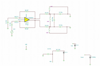
First off, I wanted to provide you with a description of what changes were made to the evaluation board. Below is the schematic in the simulation tool TINA. The schematic I altered is the one found in the THS4541 EVM User’s guide. In short, the transformer after the amplifier was taken out and the resistor values were adjusted, so the gain would be like what is seen in Seeker X which is about a gain of 10. The parts that were changed are: R26 and R27 were taken out, R7 and R8 were changed to 27.4 ohms, R5 and R6 became 287 ohms, R13 and R14 are now 25 ohms and lastly R15 is now a 33-pF capacitor followed by R20 and R21 being the same value capacitor.
Measurements were made with the following values for supplies and signal generators: 3V with 0.5 A supply for Vin, 0.9V and 0.08A supply for Vocm and 36 MHz at a -30 dBm level.
At first, we used the above to see whether the amplifier was working. Afterwards, we took off the signal to run some observations.
*The following notes are with no signal
When I started measurements using the scope, I saw a differential output difference around 1.2V with the positive side of the signal being at 1.5V and the negative side of the signal measuring at 0.3387V. The differential output that I am expecting is around 0V.
So, when I saw a difference of 1V, I probed to see whether the input voltage for Vocm is as expected, and it falls near 0.9V which is as expected from the datasheet.
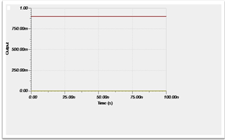
Above is the TINA simulation when the input signal is removed. I’m wondering if you can give me an explanation as to why there is a discrepancy between the simulation and what I see in lab with the circuit at DC conditions. In addition, do you have any ideas for schematic changes or maybe different part that could be used in substitute of this amplifier to get a desired output?


