This thread has been locked.

If you have a related question, please click the "Ask a related question" button in the top right corner. The newly created question will be automatically linked to this question.

XTR300: linearity vs temperature

Part Number: XTR300
Other Parts Discussed in Thread: TIPD155

Tool/software:

Hello Team, 

can you please help: 

I have been working with the XTR300 component for a few days now and would like to know which TK
I can assume for this component.

In the data sheet I find these entries:

We would like operate the XTR300 in a temperature range from -40 to 80°C with up to 21mA
in a temperature range of -40 to 80°C.


Is it correct that I have a TC of up to (Delta T = 120°C) 1200ppm over the temperature range in the WC?
over the temperature range?
The RGAIN is
10k 0.1% 25ppm

Do you know measures to counteract this?

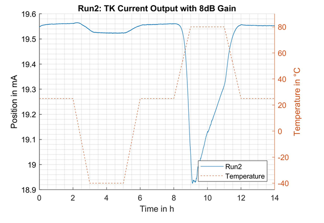
My first measurement looks like this:

  • The minimum value 18.924mA
  • The maximum value is 19.565mA
  • Is the deviation of 640µA within the spec?
  • Hi Jan,

    The gain error drift of the XTR300 is ±3.6ppm/°C typical and ±10ppm/°C maximum over temperature.  A temperature change of -40C to +80C temp change, (delta of 120°C) corresponds to a change of 1200ppm in the gain error. This is worst case, based on max spec for the XTR300 stand alone when using a high-precision, low drift resistor to set the gain of the device.

    The XTR300 transfer function for the current output mode is below, which involves the RSET resistor, and the optional ROS resistor, and external reference in some circuits:

    What is the temperature coefficient of the RSET resistor? Is this also 25ppm/°C? If the RSET resistor drifts 25ppm/°C, then the current of the XTR300 will drift as a function of the RSET resistor temperature coefficient; and you will need to choose a lower drift resistor.  A 25ppm/°C resistor can drift up to 3000ppm worst case over a 120°C temperature change,

    Please review the application note below. The application note explains the total error analysis of the complete XTR300 circuit, accounting for the external DAC and passive component specifications.

    The reference design: 'Two-Channel Source/Sink Combined Voltage & Current Output, Isolated, EMC/EMI Tested Reference Design' (TIPD155) documents in good detail the calculation of TUE for current mode on pages 9-10:

    Please find a link for the TIPD155 reference design below:

    TIPD155 User Guide:

    Two-Channel Source/Sink Combined Voltage & Current Output, Isolated, EMC/EMI Tested Reference Design

    TIPD155 Reference Design web page:
    Two-Channel Source/Sink Combined Voltage & Current Output, Isolated, EMC/EMI Tested Reference Design

    Thank you and Regards,

    Luis


  • Hi Jan,

    Please provide a full schematic providing the % tolerance and drift of the resistors, and also specify what circuit is generating the input voltage of the XTR300 and the accuracy and drift of this input signal source.

    Also, on the test setup, please explain what instrument or circuit is used to measure the output current.

    Thank you and Regards,

    Luis

  • Hello Luis, 

    I got the following reply: 

    First of all, thank you for the feedback.
    In the meantime I have measured another DUT where the TC fits more in the region I expected.
    Around 20ppm/°C in my setup.

    I am now looking for the difference between the two DUTs.

    I would like to know whether I can add the two TCs for “Gain Nonlinearity” and “Gain Error” and thus assume around 16ppm/°C.

    Jna

  • Hi Jan,

    I am now looking for the difference between the two DUTs.

    I would like to know whether I can add the two TCs for “Gain Nonlinearity” and “Gain Error” and thus assume around 16ppm/°

    Since the gain error and the linearity gain error are considered uncorrelated, provided that you are consistent with the units, an estimate of total error at certain temperature can be calculated by taking the root of the sum of squares (RSS) of the individual errors, accounting for their temp drift. 

    For example, if you needed to estimate the errors at +80°C:

    % Gain Error at +80°C = % GE @ 25°C + (GE_Drift ppm/°C) * (80°C - 25°C) * (1E4)

    % Gain Error at +80°C = 0.04% + (3.6 ppm/°C) * (80°C - 25°C) * (1E4)

    % Linearity Error at +80°C = % Linearity @ 25°C + (Linearity_Drift ppm/°C) * (ΔTemp °C) * (1E4)

    % Linearity Error at +80°C = 0.01% + (1.5 ppm/°C) * (80°C - 25°C) * (1E4)

    % Estimate of total Error at Temp = √ { (% Gain Error at +80°C )^2 + (% Linearity Error at +80°C)^2 + (% Offset Error at +80°C)^2 }

    Thank you and Regards,

    Luis