This thread has been locked.

If you have a related question, please click the "Ask a related question" button in the top right corner. The newly created question will be automatically linked to this question.

INA129: Pin numbers and labels in SPICE model don't match datasheet

Part Number: INA129
Other Parts Discussed in Thread: INA128

Tool/software:

I'm trying to run simulations on INA129 and I'm using the model in PSpice for TI, but surprisingly the pin numbers & names in the model don't match the ones in datasheet.

The model has 10 pins and datasheet has 8 pins only. What am I missing?

Below is the comparison of the pin numbers, middle column is from datasheet and third column is from spice model:

Pin 1: RG / VIN+

Pin 2: VIN- / VIN-

Pin 3: VIN+ / V+

Pin 4: V- / V-

Pin 5: REF / VO

Pin 6: VO / -

Pin 7: V+ / -

Pin 8: RG / REF

Pin 9: - / RG

Pin 10: - / RG

  • Arash,

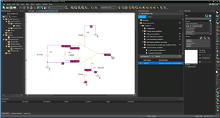
    Using PSpice for TI I built a schematic with INA129.  I put the amplifier in a gain of 10V/V and applied an input signal of 0.1V and simulated an output signal of 1.00V/V.  This is the expected operation for the device.  The model that I am looking at does not show any schematic pin numbers.  I do not see the same issues that you are seeing.  Note: I built the schematic in PSPICE for TI using the integrated library and searching for INA128 (see right hand side of screen shot). 

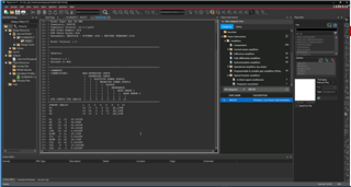
    I think you may be importing this into another simulator.  The model header indicates the pin function.  This mapping doesn't correspond to actual device pins but just the model mapping.  See second screen shot below.

    I hope this helps.  If not, please add follow up details.

    Best regards, Art